Copyright © 2015 Avnet, Inc. AVNET and the AV logo are registered trademarks of Avnet, Inc. All other brands are property of their respective owners.
Avnet Electronics Marketing 11 of 28 Rev D 24 Apr 2015
2.2 Clocks
2.2.1 Triple Output User programmable Texas Instruments CDCE913 clock
The CDCE913 is a modular PLL-based low-cost, high-performance, programmable clock synthesizer,
multiplier, and divider. It can generate up to 3 output clocks from a single input frequency. Each output can be
programmed via an SDA / SCL, SMBus / I2C interface, for any clock frequency up to 230 MHz, using the
integrated configurable PLL. The input crystal frequency on the S6LX9 MicroBoard is 27 MHz. The
following clock frequency outputs are pre-programmed into the CDCE913 during factory configuration.
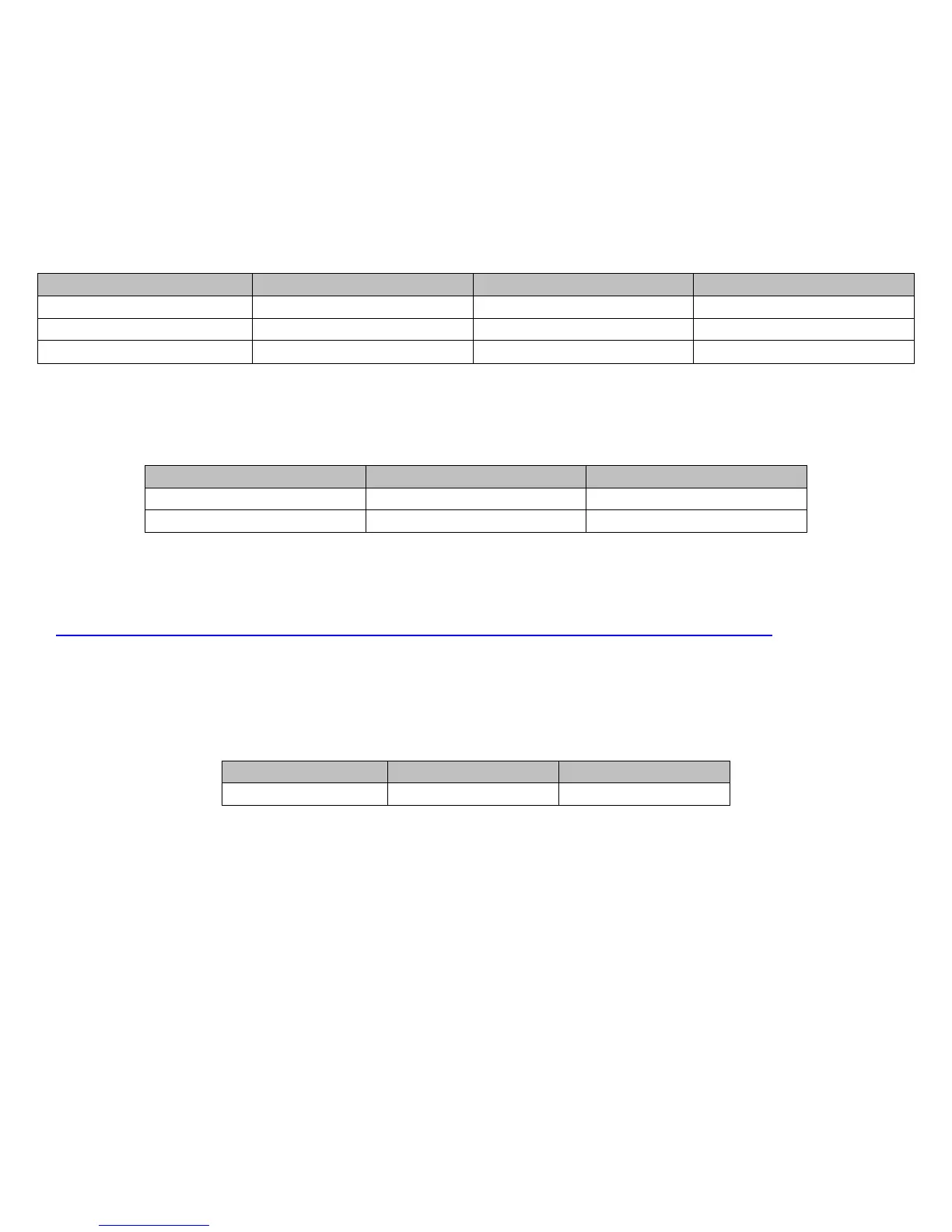
Table 2 – CDCE913 Clocks
Clock CDCE913 Pin# Signal Name FPGA Pin#
40 MHz U1 pin 11 (Y1) USER_CLOCK V10 (GCLK0)
66.7 MHz U1 pin 9 (Y2) CLOCK_Y2 K15 (GCLK9)
100 MHz U1 pin 8 (Y3) CLOCK_Y3 C10 (GCLK13)
The user is able to modify these frequencies using the FPGA’s connection to the CDCE913 I2C port. Internal
FPGA pull-ups are required for this interface to work properly
Table 3 – CDCE913 I2C
Signal Name CDCE913 Pin# FPGA Pin#
SDA U1 pin 13 U13
SCL U1 pin 12 P12
NOTE: The CDCE913 is pre-programmed to operate in spread spectrum mode to reduce emissions. See the
following forum post for additional explanation:
http://community.em.avnet.com/t5/Spartan-6-LX9-MicroBoard/LX9-MicroBoard-Clock-Problem/td-p/6858
2.2.2 Optional 66.6 MHz Maxim low-cost, fixed-frequency oscillator
This is an unpopulated Maxim 3.3V low-cost oscillator, part number DS1088LU-66+.
Table 4 – 66 MHz Clock
Clock Signal Name FPGA Pin#
66.7 MHz BACKUP_CLOCK R8 (GCLK31)
 Loading...