Copyright © 2015 Avnet, Inc. AVNET and the AV logo are registered trademarks of Avnet, Inc. All other brands are property of their respective owners.
Avnet Electronics Marketing 20 of 28 Rev D 24 Apr 2015
2.6 User Interfaces
2.6.1 User LEDs
Four discrete “High Brightness, Low Vf ” LED’s are installed on the board and can be used to display the status
of the internal logic. These LEDs are attached as shown below and are lit by forcing the associated FPGA I/O
pin to a logic ‘1’ and are off when the pin is either low (0) or not driven.
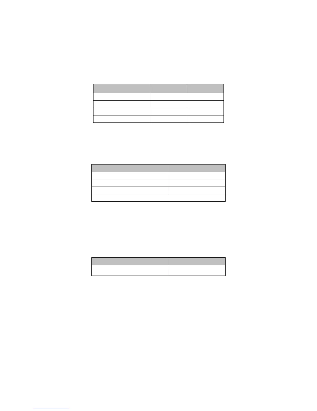
Table 12 – LED Pin Assignments
Net Name Reference FPGA Pin#
FPGA_GPIO_LED1 D2 P4
FPGA_GPIO_LED2 D3 L6
FPGA_GPIO_LED3 D9 F5
FPGA_GPIO_LED4 D10 C2
2.6.2 Four configurable FPGA user DIP switches (TE Connectivity 1571983-4)
Table 13 – FPGA Dip Switches
FPGA DIP Switch FPGA Pin#
FPGA_DIP1 B3
FPGA_DIP2 A3
FPGA_DIP3 B4
FPGA_DIP4 A4
Please note that internal pulldowns are required for these pins.
2.6.3 One configurable FPGA user push-button (TE Connectivity 8-1437565-0)
Table 14 – FPGA Push Button
FPGA Push-button FPGA Pin#
USER_RESET_N V4
Please note that an internal pulldown is required for this pin.
 Loading...