Copyright © 2015 Avnet, Inc. AVNET and the AV logo are registered trademarks of Avnet, Inc. All other brands are property of their respective owners.
Avnet Electronics Marketing 16 of 28 Rev D 24 Apr 2015
2.4 Communication
2.4.1 Universal Serial Bus (USB) 2.0, Full Speed USB-to-JTAG bridge via Atmel AT90USB162 /
ATMEGA162U2 AVR Microcontroller and TE Connectivity USB-A connector
P1 is a TE Connectivity USB-A board-mount connector. P1 connects to a full-speed (12 Mbps) USB peripheral
port on the AT90USB162 / ATMEGA162U2 device. Power supplied by the USB host via connector P1
(+5V_USB_A) is used in conjunction with power from the other USB port, through diodes D13 and D16 to
power the S6LX9 board.
The AT90USB162 / ATMEGA162U2 is used to control FPGA configuration via the Digilent JTAG interface
and also to directly program the SPI Flash via a Digilent program. JTAG configuration is accomplished using
iMPACT and the Digilent Plug-in. Please see the Xilinx Spartan-6 LX9 MicroBoard - Configuration Guide
located at www.em.avnet.com/s6microboard for a User Guide on this subject.
Communicating directly to the SPI Flash is accomplished using the command line sfutil.exe. Both
configurations make use of custom Digilent firmware loaded into the AT90USB162 / ATMEGA162U2 device
during manufacture. The SPI Flash Interface Pinout is shown in Table 6. The JTAG Interface Pinout is shown in
Table 7.
Note that an additional Xilinx Platform Cable connector is provided (J6), for JTAG operation.
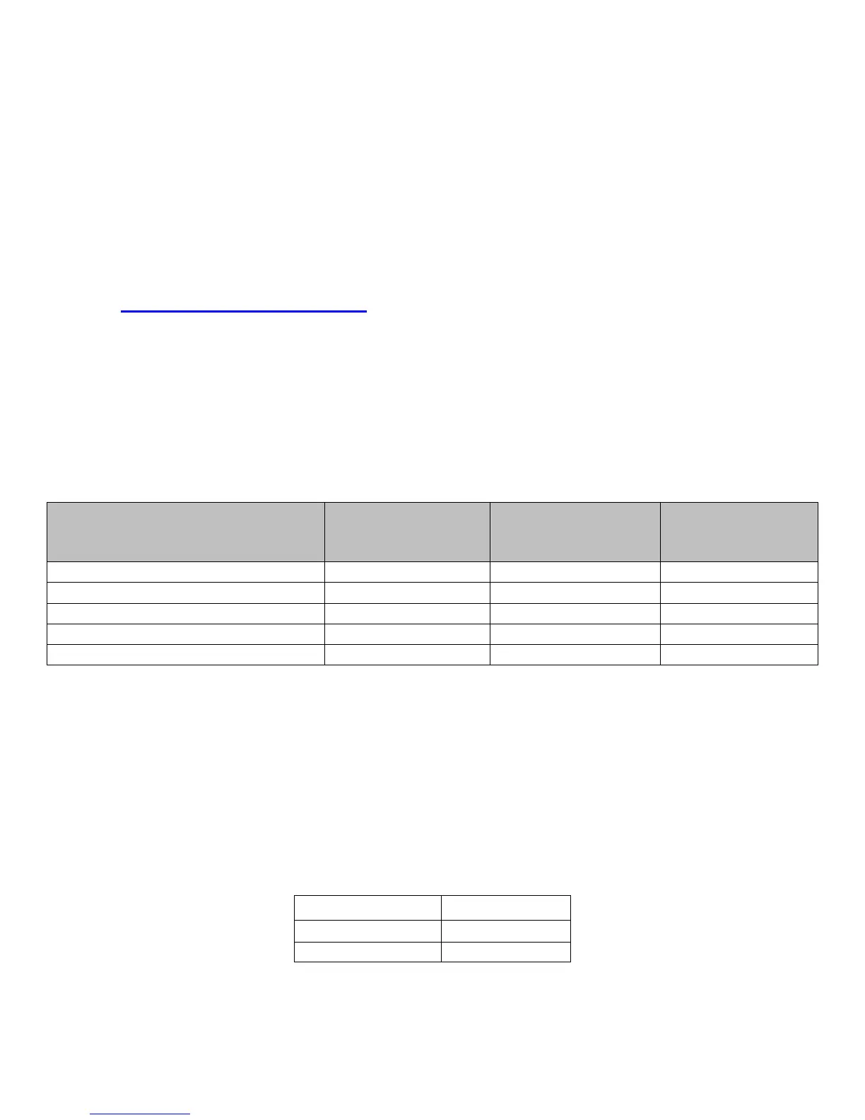
Table 7 – USB-JTAG Signals
Signal Xilinx Parallel IV
Pin#
FPGA
Pin#
AT90USB162 /
ATMEGA162U2
Pin#
FPGA_TCK J6 pin 6 (TCK) A17 (TCK) U3 pin 15 (SCLK)
FPGA_TMS J6 pin 4 (TMS) B18 (TMS) U3 pin 14 (SS_N)
FPGA_TDO J6 pin 8 (TDO) D16 (TDO) U3 pin 17 (MISO)
FPGA_TDI J6 pin 10 (TDI) D15 (TDI) U3 pin 16 (MOSI)
FPGA_PROG NC V2 (PROGRAM_B) U3 pin 19 (PB5)
2.4.2 USB-UART
The Spartan-6 FPGA LX9 MicroBoard implements a Silicon Labs CP2102 device that provides a USB-to-
UART bridge. The USB physical interface is brought out on a TE Connectivity USB micro-B connector labeled
“J3.” Power supplied by the USB host via connector J3 (+5V_USB_B) is used in conjunction with power from
the other USB port, through diodes D13 and D16 to power the S6LX9 board.
Please see the Avnet DRC for an application note describing the driver installation and usage of this device.
Table 8 – USB-to-UART Pin Locations
Net Name Spartan-6 Pin #
USB_RS232_RXD R7
USB_RS232_TXD T7
 Loading...