24 www.xilinx.com VC7222 IBERT Getting Started Guide
UG971 (v5.0) June 12, 2014
Chapter 1: VC7222 IBERT Getting Started Guide
Viewing GTH Transceiver Operation
After completing step 6 in Starting the SuperClock-2 Module, the IBERT demonstration is
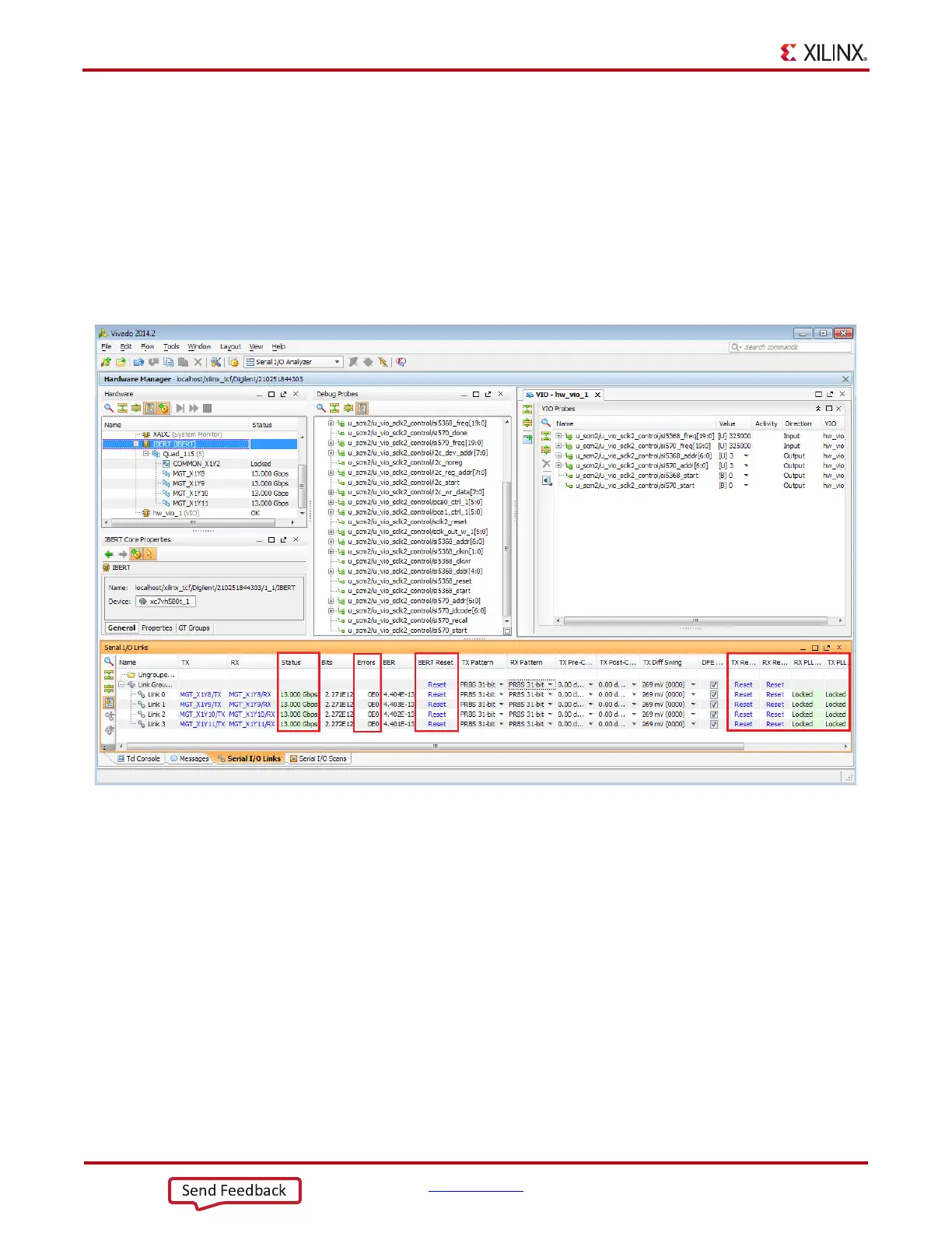
configured and running. The status and test settings are displayed on the Links tab in the
Links window shown in Figure 1-19.
Note the line rate and the error count:
• The line rate for all four GTH transceivers is 13.0 Gb/s (see the Status column in
Figure 1-19).
• Verify that there are no bit errors.
In Case of RX Bit Errors
If there are initial bit errors after linking, or as a result of changing the TX or RX pattern,
click the respective BERT Reset button to zero the count.
If the MGT Link Status shows No Link for one or more transceivers, click the
respective TX Reset button followed by BERT Reset (Figure 1-19).
Additional information on the Vivado Design Suite software and IBERT core can be found
in Vivado Design Suite User Guide: Programming and Debugging (UG908) [Ref 3] and
LogiCORE IP Integrated Bit Error Ratio Tester (IBERT) for 7 Series GTH Transceivers Product
Guide for Vivado Design Suite (PG152) [Ref 4].
X-Ref Target - Figure 1-19
Figure 1-19: Serial I/O Analyzer Links

 Loading...


