VC7222 IBERT Getting Started Guide www.xilinx.com 27
UG971 (v5.0) June 12, 2014
Running the GTZ IBERT Demonstration
Attach the GTZ Quad Connector
Before connecting the BullsEye cable assembly to the board, firmly secure the blue
elastomer seal provided with the cable assembly to the bottom of the connector housing if
it is not already inserted (see Figure 1-4).
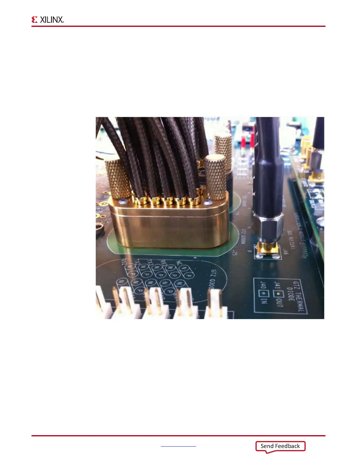
Attach the Samtec BullsEye connector to GTZ Quads Q300A and Q300B (Figure 1-22),
aligning the two indexing pins on the bottom of the connector with the guide holes on the
board. Hold the connector flush with the board and fasten it by tightening the two captive
screws.
GTZ Transceiver Clock Connection
Connect the GTZ reference clocks, CLK0 and CLK1, to the SuperClock-2 module as follows
(see Figure 1-23):
J56 (REFCLK0_P) → SMA connector → J7 (CLKOUT2_P) on the SuperClock-2 module
J57 (REFCLK0_N) → SMA connector → J8 (CLKOUT2_N) on the SuperClock-2 module
J46 (REFCLK1_P) → SMA connector → J5 (CLKOUT1_P) on the SuperClock-2 module
J47 (REFCLK1_N) → SMA connector → J6 (CLKOUT1_N) on the SuperClock-2 module
X-Ref Target - Figure 1-22
Figure 1-22: BullsEye Connector Attached to GTZ Quads Q300A and Q300B

 Loading...


