XC4000 Series Field Programmable Gate Arrays
4-38 September 18, 1996 (Version 1.04)
I/O Routing
XC4000-Series devices have additional routing around the
IOB ring. This routing is called a VersaRing. The
VersaRing facilitates pin-swapping and redesign without
affecting board layout. Included are eight double-length
lines spanning two CLBs (four IOBs), and four longlines.
Global lines and Wide Edge Decoder lines are provided.
XC4000EX devices also include eight octal lines.
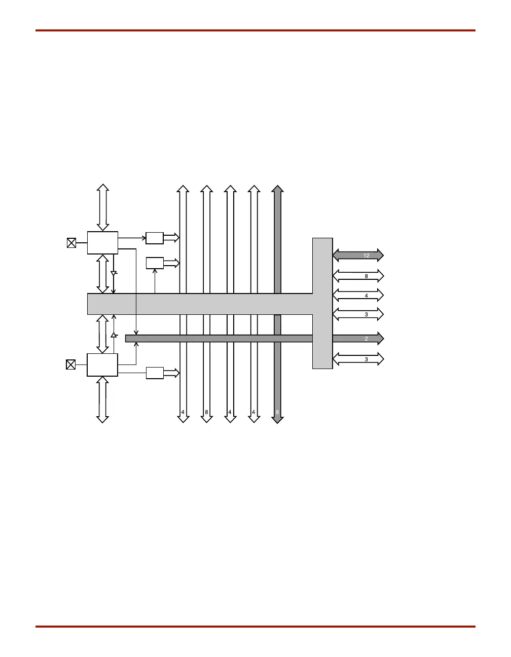
A high-level diagram of the VersaRing is shown in
Figure 32. The shaded arrows represent routing present
only in XC4000EX devices.
Figure 33 is a detailed diagram of the XC4000E and
XC4000EX VersaRing. The area shown includes two IOBs.
There are two IOBs per CLB row or column, therefore this
diagram corresponds to the CLB routing diagram shown in
Figure 27 on page 34. The shaded areas represent routing
and routing connections present only in XC4000EX
devices.
X5995
Direct
Connect
Edge
Decode
Double Long Global
Clock
Octal
Quad
Single
Double
Long
Direct
Connect
Long
INTERCONNECT
IOB
WED
WED
WED
IOB
Figure 32: High-Level Routing Diagram of XC4000-Series VersaRing (Left Edge)
WED = Wide Edge Decoder, IOB = I/O Block (shaded arrows indicate XC4000EX only)
 Loading...