ZC706 Evaluation Board User Guide www.xilinx.com 32
UG954 (v1.5) September 10, 2015
Feature Descriptions
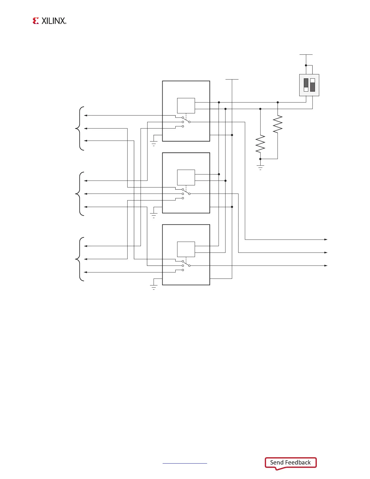
DIP switch SW4[1:2] setting 10 selects the 14-pin header J3 for configuration using either a
Parallel Cable IV (PC4) or Platform Cable USB II. DIP switch SW4 setting 01 selects the
USB-to-JTAG Digilent bridge U30 for configuration over a Standard-A to Micro-B USB cable.
DIP switch SW4 setting 11 selects the JTAG 20-pin header at J62. The four JTAG signals TDI,
TDO, TCK, and TMS would be connected to J62 through flying leads from a JTAG cable. The
3-to-1 analog switch settings are shown in Table 1-11.
X-Ref Target - Figure 1-10
Figure 1-10: PL JTAG Programming Source Analog Switch
UG954_c1_10_041113
SDA02H1SBD
SW4
VCC3V3
43
JTAG_SEL_1
JTAG_SEL_2
R20
4.7kΩ
0.1 W
5%
R21
4.7kΩ
0.1 W
5%
GND
12
JTAG_TCK
U47
TS5A3359
SP3T
ANALOG SWITCH
1
2
3
4
GND
8
6
5
7
IN2
IN1
V+
U46
TS5A3359
SP3T
ANALOG SWITCH
1
2
3
4
GND
8
6
5
7
IN2
IN1
V+
U45
TS5A3359
SP3T
ANALOG SWITCH
1
2
3
4
GND
8
6
5
7
IN2
IN1
V+
NO1
NO2
NO0
COM
NO1
NO2
NO0
COM
NO1
NO2
NO0
COM
VCC3V3
JTAG_TMS
JTAG_TDI
14PIN_JTAG_TCK
14PIN_JTAG_TDI
14PIN_JTAG_TMS
DIGILENT_TCK
DIGILENT_TMS
DIGILENT_TDI
20PIN_JTAG_TCK
20PIN_JTAG_TMS
20PIN_JTAG_TDI
To J3
Parallel Cable or
Platform Cable
(14 pins)
To U30
USB-to-JTAG
Digilent bridge
To J62
Parallel Cable
(20 Pins)

 Loading...


