ZC706 Evaluation Board User Guide www.xilinx.com 57
UG954 (v1.5) September 10, 2015
Feature Descriptions
Ethernet PHY User LEDs
[Figure 1-2, callout 21]
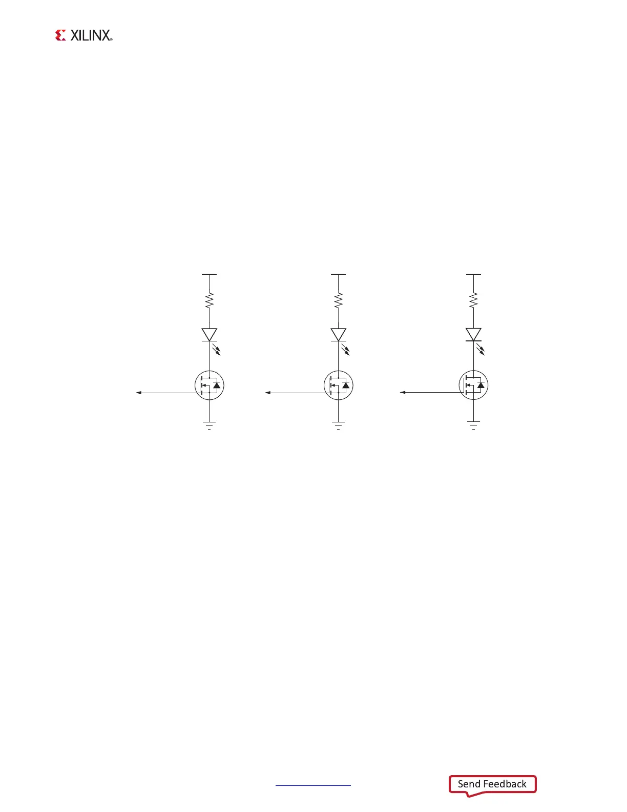
The three Ethernet PHY user LEDs shown in Figure 1-24 are located near the RJ45 Ethernet
jack P3. The on/off state for each LED is software dependent and has no specific meaning at
Ethernet PHY power on.
Refer to the Marvell 881116R Alaska Gigabit Ethernet transceiver data sheet for details
concerning the use of the Ethernet PHY user LEDs. They are referred to in the data sheet as
LED0, LED1, and LED2. See the data sheet and other product information for the Marvell
881116R Alaska Gigabit Ethernet Transceiver [Ref 24].
User I/O
[Figure 1-2, callout 22–24]
The ZC706 evaluation board provides the following user and general purpose I/O
capabilities:
• Four user LEDs (callout 22)
°
GPIO_LED_LEFT DS8, GPIO_LED_CENTER DS9, GPIO_LED_RIGHT DS10,
GPIO_LED_0 DS35
• Three user pushbuttons (callout 23)
°
GPIO_SW_LEFT SW7, GPIO_SW_CENTER SW9, GPIO_SW_RIGHT SW8
• PL CPU reset pushbutton
°
PL_CPU_RESET SW13
• 4-position user DIP Switch (callout 24)
X-Ref Target - Figure 1-24
Figure 1-24: Ethernet PHY User LEDs
UG954_c1_24_041113
1
3
2
Q4
NDS331N
460 mW
DS30
VCC3V3
PHY LED 2
1
3
2
Q6
NDS331N
460 mW
DS28
VCC3V3
PHY LED 0
388
261Ω
0.1W
1
3
2
Q5
NDS331N
460 mW
DS29
VCC3V3
PHY LED1
387
261Ω
0.1W
GNDGNDGND
386
261Ω
0.1W

 Loading...


