ZC706 Evaluation Board User Guide www.xilinx.com 63
UG954 (v1.5) September 10, 2015
Feature Descriptions
CAUTION! Do NOT plug a PC ATX power supply 6-pin connector into J22 on the ZC706 Evaluation
Board. The ATX 6-pin connector has a different pinout than J22. Connecting an ATX 6-pin connector
into J22 will damage the ZC706 Evaluation Board and void the board warranty.
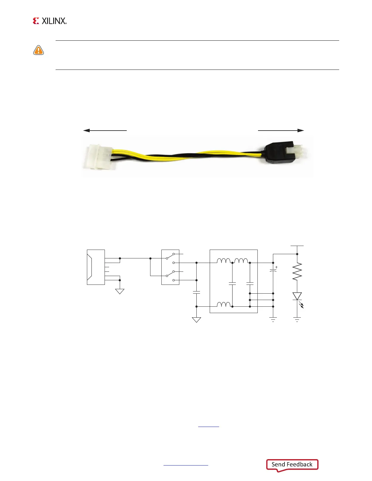
The ZC706 evaluation kit provides the adapter cable shown in Figure 1-29 for powering the
ZC706 board from the ATX power supply 4-pin peripheral connector. The Xilinx part number
for this cable is 2600304, and is equivalent to Sourcegate Technologies part number
AZCBL-WH-1109-RA4. For information on ordering this cable, see [Ref 36].
Figure 1-30 shows the power connector J22, power switch SW1 and indicator LED DS22.
Program_B Pushbutton
[Figure 1-2, callout 28]
Switch SW10 grounds the XC7Z045 AP SoC PROG_B pin when pressed. This action clears the
programmable logic configuration. The FPGA_PROG_B signal is connected to XC7Z045
AP SoC U1 pin Y9.
See 7 Series FPGAs Configuration User Guide, (UG470
) for further details on configuring the
7 series FPGAs.
X-Ref Target - Figure 1-29
Figure 1-29: ATX Power Supply Adapter Cable
X-Ref Target - Figure 1-30
Figure 1-30: Power On/Off Switch SW1
UG954_c1_29_041113
To ATX 4-Pin Peripheral
Power Connector
To J22 on ZC706 Board
UG954_c1_30_041113
VCC12_P_IN
VCC12_P
R171
2.15kΩ
.1W
1%
INPUT_GND
1
2
3
4
SW1
GND
C568
330 μF
25V
C319
1μF
25V
GND
DS22
5
6
J22
1
2
3
4
5
6
12V
N/C
COM
12V
N/C
COM
INPUT_GND
U18 50Ω
1
3
8
7
6
5
1
2
1
2
1
2