10
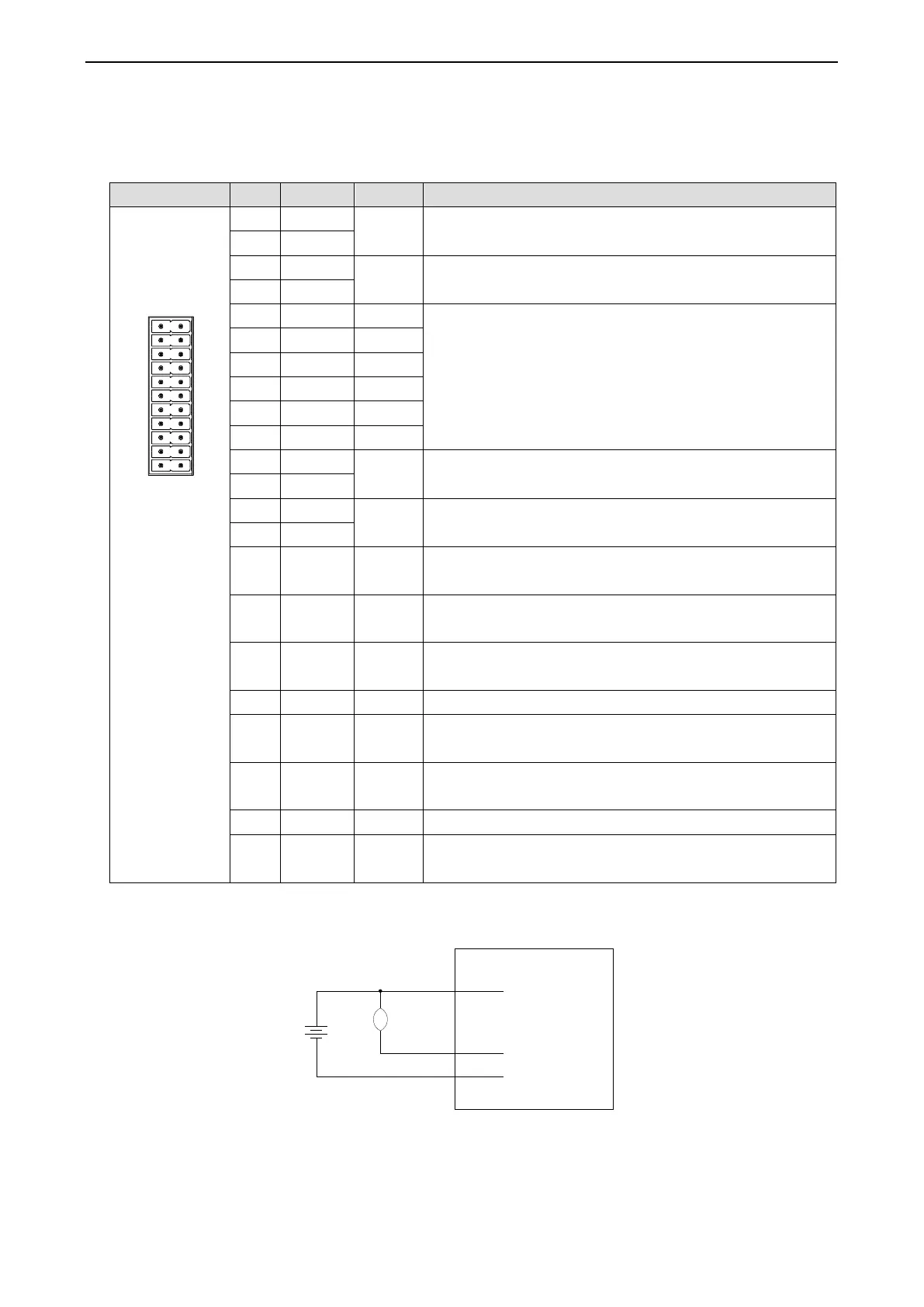
3-3. Control signal interface
3-3-1. Interface functions
1
3
5
7
9
11
13
15
17
19
21
2
4
6
8
10
12
14
16
20
22
18
Differential input signal SI1, 24V effective, maximum input
frequency 200kHz, default probe input signal 1
Differential input signal SI2, 24V effective, maximum input
frequency 200kHz, default probe input signal 2
Single ended input signals SI3~SI7, 12~24V valid,
maximum input frequency 10kHz, signal definition is
configurable. I3 default is origin, I4 and I5 default is
positive and negative limit, I6 and I7 default is in common
use. COMI is the common end of single ended input signal,
with common positive or negative
Differential output signal OUT1, maximum output current
100mA, withstand voltage 30VDC, default alarm output
Differential output signal OUT2, maximum output current
100mA, withstand voltage 30VDC, default in place signal
Single ended output, common cathode, maximum current
100mA, withstand voltage 30VDC
Single ended output, common cathode, maximum current
100mA, withstand voltage 30VDC
Single ended output, common cathode, maximum current
100mA, withstand voltage 30VDC
Used together with brake output
Single ended output, common cathode, maximum current
100mA, withstand voltage 30VDC
Brake positive output, maximum 500mA, is displayed as
SO7 in upper computer
Output common cathode common terminal
Brake negative output, maximum 500mA, is displayed as
SO7 in upper computer
DP3C series driver has a brake output and integrated freewheeling diode. The driving current is up to 500mA. It
can directly drive the brake without relay. The circuit diagram of holding brake is as follows:
 Loading...


