45
NOTCH, CONT/APF
The NOTCH center frequency can be returned
to the initial value by pressing and holding the
[NOTCH] key.
The center frequency of the set contour and the
center frequency of the audio peak lter can be re-
turned to their initial values by pressing and holding
the [CONT/APF] key.
Inner Knob (NOTCH)
Rotate the inner [NOTCH] knob to adjust the cen-
ter frequency of the IF NOTCH filter. Press the
[NOTCH] key to turn the IF NOTCH filter ON or
OFF.
The null position of the IF NOTCH lter can be ob-
served on the display.
Additionally, the display will show the center fre-
quency of the IF NOTCH lter for 2 seconds when-
ever the [NOTCH] knob is turned.
Outer Knob (CONT/APF)
The DSP CONTOUR operation can alter the prole
of the passband to partially attenuate an in-band
frequency component.
The CONTOUR operation can be switched ON/
OFF with the [CONT/APF] Key.
The inuence of CONTOUR is depicted graphically
on the display.
If there is interference or noise during CW opera-
tion, the APF center frequency is automatically set
to the CW PITCH frequency as a “peak filter”, to
make it easier to hear the desired signal.
APF operation is switched ON/OFF with the [CONT/
APF] key.
The location of the APF peak frequency is graphi-
cally illustrated on the display.
When the knob is turned, the center fre-
quency of NOTCH, the center frequency
of CONTOUR, or the Peak Frequency shift
width of the of the APF will be illustrated on
the display for 2 seconds.
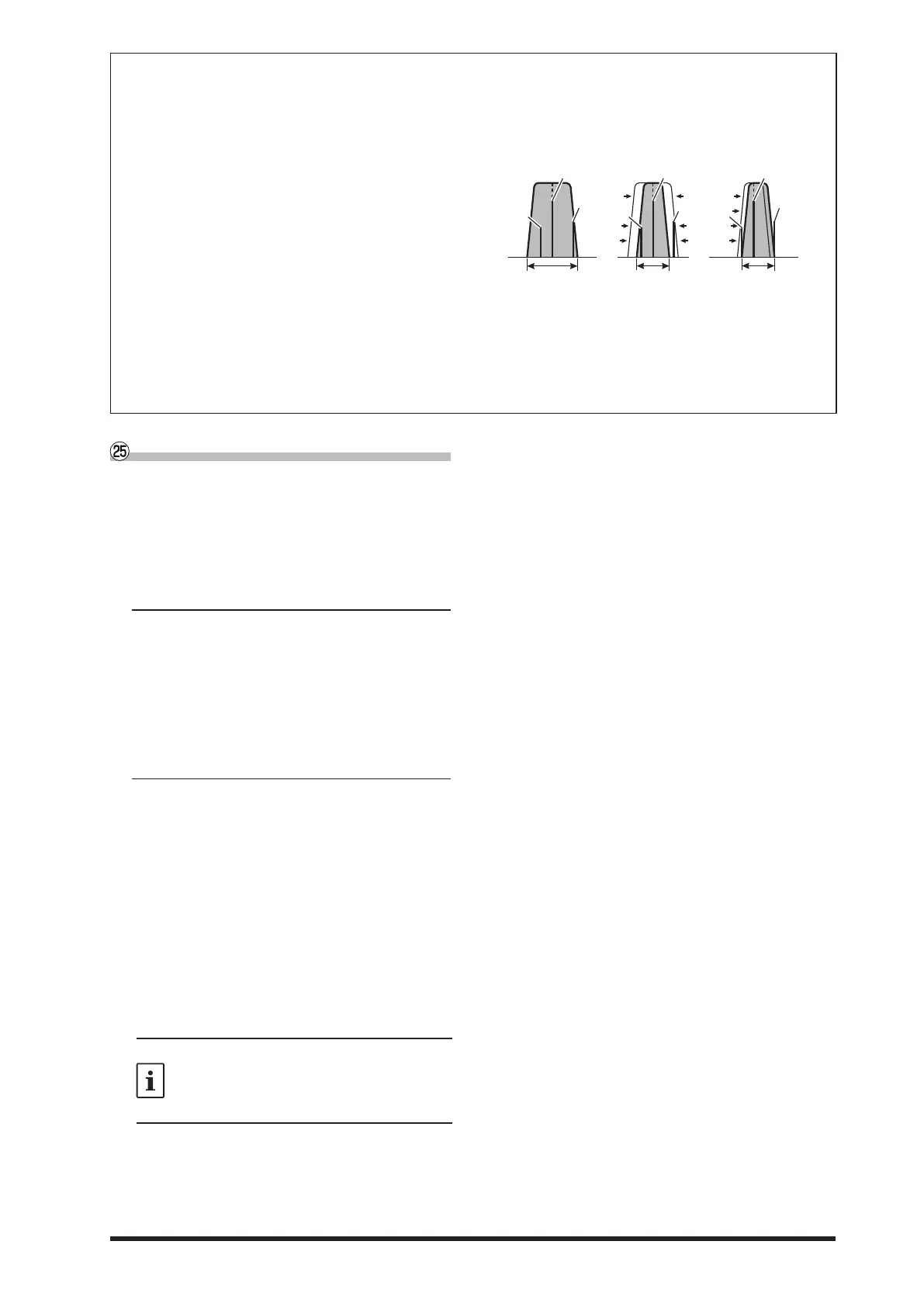
Using IF SHIFT and WIDTH Together
The IF SHIFT and Variable IF WIDTH features together form a very eective interference-ghting l-
tering system.
For example, in Figure “A", you can see how in-
terference has appeared both on the high and low
sides of the desired signal.
Rotate the [WIDTH] knob, the interference from one side
can be eliminated (Figure “B”). Next, rotate the [SHIFT]
knob to re-position the passband (Figure “C”), the inter-
ference on the opposite side can be removed, without
re-introducing the interference previously eliminated in
Figure “B”.
IF BANDWIDTH IF BANDWIDTH IF BANDWIDTH
BA
Desired Signal Desired Signal Desired Signal
QRM QRM
QRM QRM
QRM
For best interference reduction, the WIDTH and SHIFT features are the primary tools you should use. After nar-
rowing the bandwidth (WIDTH) and/or adjusting the center of the passband (SHIFT), the Contour control may
then yield additional signal-enhancement benets on the net residual bandwidth. Even more, the IF NOTCH Filter
(described later) may also be used, in conjunction with these lter systems, to signicant advantage.

 Loading...