4
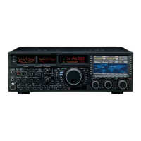
General Description
Hybrid SDR conguration inherited from the FTDX101 series
In addition to the narrow band SDR receiver that boasts awesome basic performance, the FTDX10 has a
hybrid SDR conguration utilizing an integrated direct sampling SDR receiver, which permits visualization
of the entire band spectrum in real time.
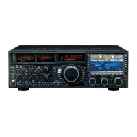
By adopting the hybrid SDR method, and utilizing the features of the direct sampling method, it is possible
to display a wide-view of the information in the entire band in real time, and improve the performance of
the complete receiving circuit with the narrow band SDR technology down conversion method.
Comes equipped with three types of roong lters
This transceiver is equipped with three types of roong lters for 500 Hz, 3 kHz and 12 kHz bandwidths.
These narrow band lters are especially useful on a very crowded band during contests, because they
can dramatically attenuate powerful out-of-band signals in the rst IF stage, and thus reduce their impact
in the second stage. Further, the excellent dynamic range and IP3 characteristics optimize the processing
of all signals ranging from faint to powerful.
Adopts 3DSS/Hybrid Dual SDR Display
In addition to the conventional waterfall display, a 3DSS (3 Dimensions Spectrum Stream) image method
has been newly adopted. The 3DSS image uses the horizontal axis (X axis) for frequency, the vertical
axis (Y axis) for signal intensity, and the Z axis for time. Compared to the conventional waterfall method,
the signal strength is displayed in three dimensions as well as in color, recognition of changes in the band
conditions is instant, convenient and intuitive.
High-brightness TFT full-color display with touch-panel functionality
The FTDX10 is equipped with a 5-inch full-color TFT display. Operating functions, including the receiving
band noise and signal interference reduction tools, are graphically displayed. Even while involved in rig-
orous operations, such as DXpeditions and contests, the operator may instantly grasp the status of each
function.
Filter Function Display monitors the status of the passband
In the upper part of the display, a lter function display presents the state of the pass-band. In addition to
the operating state of the interference removal functions, the lter function information is displayed. Not
only can you grasp the operating status of WIDTH, SHIFT, NOTCH and CONTOUR at a glance, you can
also view the status of the RF spectrum in the passband.
Two selectable RF Stages amplify the desired signals from low band to
high band
RF amplifier AMP1, and AMP2 are low noise negative feedback RF amplifiers that may be selected or
combined in series as is needed for various low-band, high-band, frequency and noise conditions.
In addition, the IPO (Intercept Point Optimization) function maximizes the dynamic range and enhances
the close multi-signal and inter-modulation characteristics of the receiver. The inuence of strong broad-
casting stations, especially in the low bands, can be minimized.
WIDTH and the continuously variable Bandwidth SHIFT features per-
mit elimination of interfering signals
The WIDTH feature allows the bandwidth to be narrowed by rotating the WIDTH knob. The SHIFT feature,
can eliminate interference in one side of the passband. Often, weak signals disappear due to interfering
signals (including pile-ups). The interfering signals may be extracted, leaving only the desired signal, be-
cause of the unique DSP sharp ltering characteristics.
CONTOUR feature is renowned for eective noise reduction
Rather than using the DSP extremely sharp attenuation characteristics, the CONTOUR circuit provides
gentle shaping of the DSP passband lter, and can thus attenuate or peak bandwidth components in seg-
ments. The interfering signal can be naturally shaped without having part of the signal suddenly disrupted.
The contour function is very eective in making the desired signal rise out of the interference.

 Loading...