Controller Safety 2200 YRM 1067
NOTE: The dash indicator will display the code: EP
107 (or a higher number) for 1 to 2 seconds every time
the key switch is turned to the ON position. The ZAPI
handset similarly displays V1.07 (or higher). This code
represents the EEPROM software version and DOES
NOT INDICATE A FAULT CODE.
Troubleshoot the fault using a ZAPI™ handset or a
properly configured IBM compatible PC. On trucks
equipped with the optional dash display, the dash
wiring harness plugs into the controller in place of the
LED. The display also has a red LED, however, it does
not flash codes. If a fault occurs, the red LED blinks,
the wrench LCD is shown, and "AL" followed by the
fault number is displayed.
PRINCIPLES OF OPERATION
The ZAPI™ transistor motor controller uses a sophisti-
cated microprocessor to control the logic and operation
of the controller, eliminating the need for forward and
reverse contactors. The SEM motor controller operates
on the principle of controlling the motor field circuit and
the motor armature circuit independently. The controller
has many programmable features, including maximum
speed, acceleration rate, release braking, and braking
current limit. The SEM controller includes a full range
of features, as well as diagnostic and setup capability.
NOTE: There are no user-serviceable parts in the
ZAPI™ controller. No attempt should be made to open,
repair, or otherwise modify the controller. Doing so
may damage the controller and will void the warranty.
Controller Safety
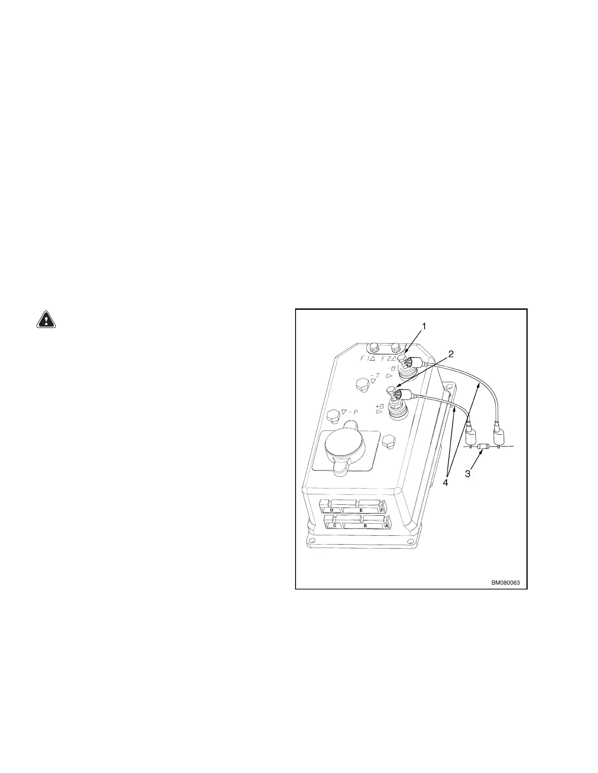
WARNING
The ZAPI™ controllers can hold an electrical charge
for several minutes after the key switch has been
turned OFF. To prevent injury, discharge the con-
trollers by connecting a 200-ohm, 2-watt resistor
between the battery positive connector and battery
negative connector on the controller and hold there
for 5 seconds.
SeeFigure2.
1. NEGA
TIVE CONNECTION
2. POSITIVE CONNECTION
3. 200-OHM, 2-WATT RESISTOR
4. INSUL
ATED JUMPER WIRES
Figur
e 2. Discharging Controller MPW045/050-E
2
 Loading...