ZAPI™ PC Interface 2200 YRM 1067
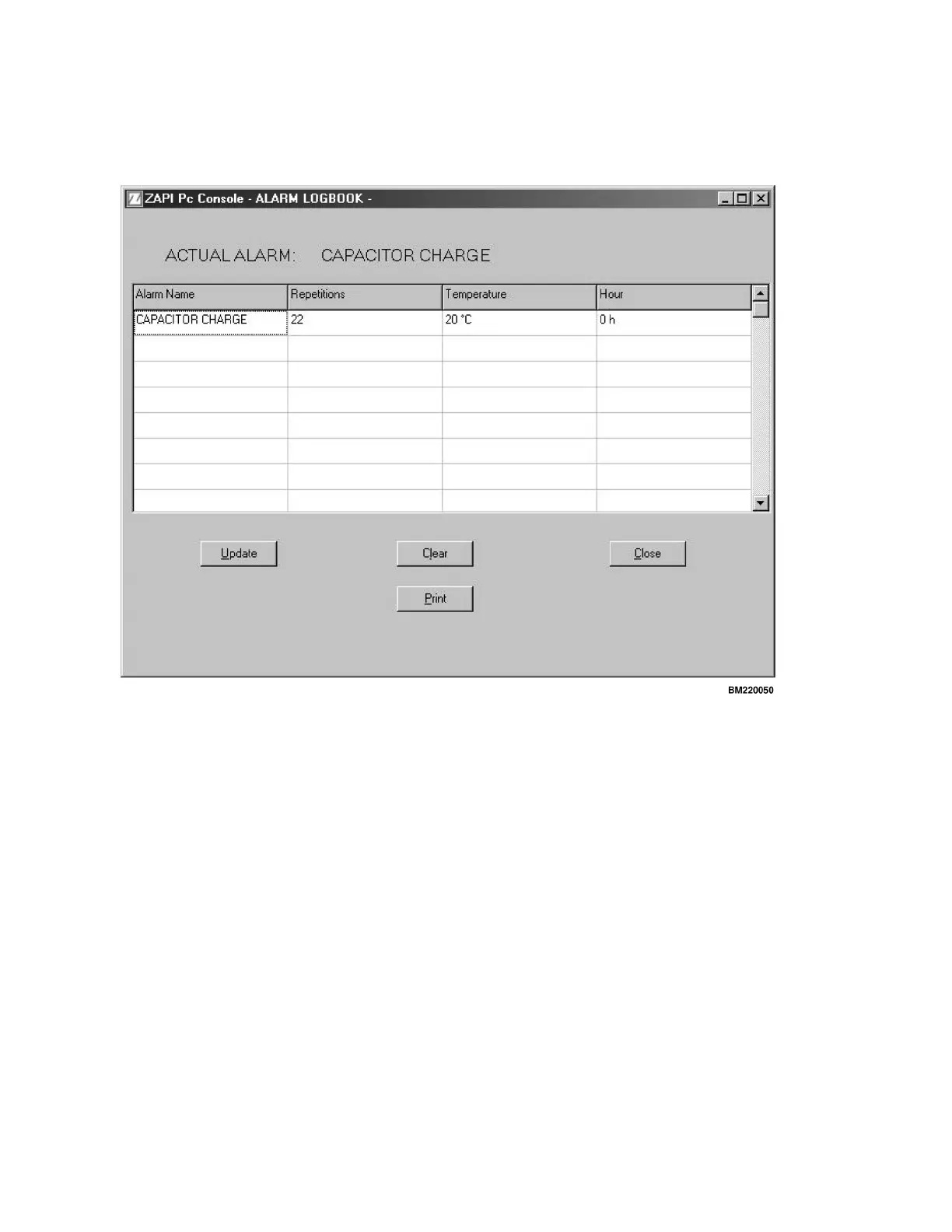
The display screen (Figure 40) will display any current
"live" alarms. Note the display ACTUAL ALARM that
indicates a current "live" alarm condition.
Figure
40. Actual Alarm
The PC s
oftware will provide the alarm name and the
numbe
r of times it has occurred, the temperature of the
contr
oller when the alarm occurred, and the hourmeter
readi
ng (internal to the controller) of when the alarm
occur
red.
The us
er can check for new alarms by pressing the Up-
date k
ey or clear out the alarm log by pressing the Clear
key.
The fo
llowing list consists of possible alarms.
Alar
ms
1. EVP N
OT OK
2. BRAKE
DRIVER KO
3. VFIEL
DNOTOK
4. PUMP V
ACC NOT OK
5. SERIA
LERROR#1
6. WATCH
DOG
7. EEPROM
KO
8. FORW + B
ACK
9. VMN NOT
OK
10. CONTAC
TOR CLOSED
11. I=0 EVE
R
12. STBY I H
IGH
13. HIGH FIE
LD CURRENT
14. NO FIELD
CURRENT
15. CAPACIT
OR CHARGE
16. LOW BATT
ERY
17. THERMAL
PROTECTION
18. CHARGIN
G BATTERY
19. POWER FA
ILURE #1
20. DRIVER SH
ORTED
21. CONTACTO
R DRIVER
22. VACC NOT O
K
23. INCORREC
TSTART
24. INPUT ERR
OR #2
25. INPUT ERR
OR #1
60
 Loading...