19
Components
EMU2579M
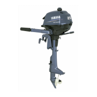
Components diagram
IP:
* May not be exactly as shown; also may not be included as standard equipment on all mod-
els.
50
EMU25802
Fuel tank
If your model was equipped with a portable
fuel tank, its function is as follows.
WARNING
EWM00020
The fuel tank supplied with this engine is
its dedicated fuel reservoir and must not
be used as a fuel storage container. Com-
mercial users should conform to relevant
licensing or approval authority regula-
tions.
11
14 15
12 13
1
2
4
3
5
6
2
7
8
9
10
ZMU05014
1. Battery cable
2. Anode(s)
3. Propeller*
4. Cooling water inlet
5. Trim tab (anode)
6. Anti-cavitation plate
7. Trim rod
8. Clamp bracket
9. Tilt support lever
10. Top cowling
11. Remote control box (side mount type)*
12. Digital tachometer*
13. Tachometer*
14. Trim meter*
15. Fuel tank*

 Loading...