14
DXS12/DXS15
B-5. SUBW4 Circuit Board
(Time required: About 4 minutes)
B-5-1 Remove the amp cover assembly. (See procedure B-1.)
B-5-2 Remove the SUBW3 circuit board.
(See procedure B-2.)
B-5-3 Remove the shield assembly. (See procedure B-3.)
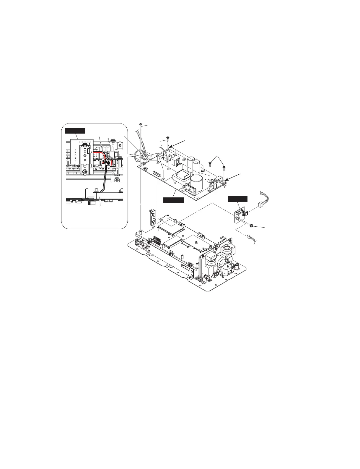
B-5-4 Remove the screw marked [370]. The SUBW4 circuit
board can then be removed. (Fig. B-4)
B-6. SUBW1 Circuit Board
(Time required: About 6 minutes)
B-6-1 Remove the amp cover assembly. (See procedure B-1.)
B-6-2 Remove the SUBW3 circuit board.
(See procedure B-2.)
B-6-3 Remove the shield assembly. (See procedure B-3.)
B-6-4 Remove the two (2) screws marked [70], three (3)
screws marked [80] and the screw marked [90]. The
shield ACIN can then be removed together with the
SUBW1 circuit board. (Fig. B-5)
* When installing the shield ACIN, fi rst tighten the two
(2) priority screws in order as shown in Fig. B-5.
* When installing the screw marked [90], tighten so
that the terminal lug points within the 90-degree
range as shown in Fig. B-5.
PRIORITY SCREW@
(優先ネジ @)
PRIORITY SCREW:
(優先ネジ :)
[220]
[220]
[370]
[220]
AMPSW
SUBW4
BINDING TIE A
(インシュロックタイ A)
DC FAN
(DC ファン)
SUBW4
Fig. B-4-1
(図B-4-1)
B-5. SUBW4 シート
(所要時間:約 4 分)
B-5-1 アンプカバー Ass'y を外します。(B-1 項参照)
B-5-2 SUBW3 シートを外します。(B-2 項参照)
B-5-3 シールド Ass'y を外します。(B-3 項参照)
B-5-4 [370] のネジ 1 本を外して、SUBW4 シートを外し
ます。(図 B-4)
B-6. SUBW1 シート
(所要時間:約 6 分)
B-6-1 アンプカバー Ass'y を外します。(B-1 項参照)
B-6-2 SUBW3 シートを外します。(B-2 項参照)
B-6-3 シールド Ass'y を外します。(B-3 項参照)
B-6-4 [70] のネジ 2 本と [80] のネジ 3 本、[90] のネジ 1
本を外して、SUBW1 シートと共にシールド ACIN
を外します。(図 B-5)
※ シールド ACIN を取り付けるときは、優先ネジ 2 本を図
に示す順番で先に締めてください。(図 B-5)
※ [90] のネジを取り付けるときは、ターミナルラグの向き
が図の通り 90 度の範囲となるように締めてください。
(図 B-5)
Fig. B-4
(図B-4)
 Loading...