9
DXS12/DXS15
[19]
[19]
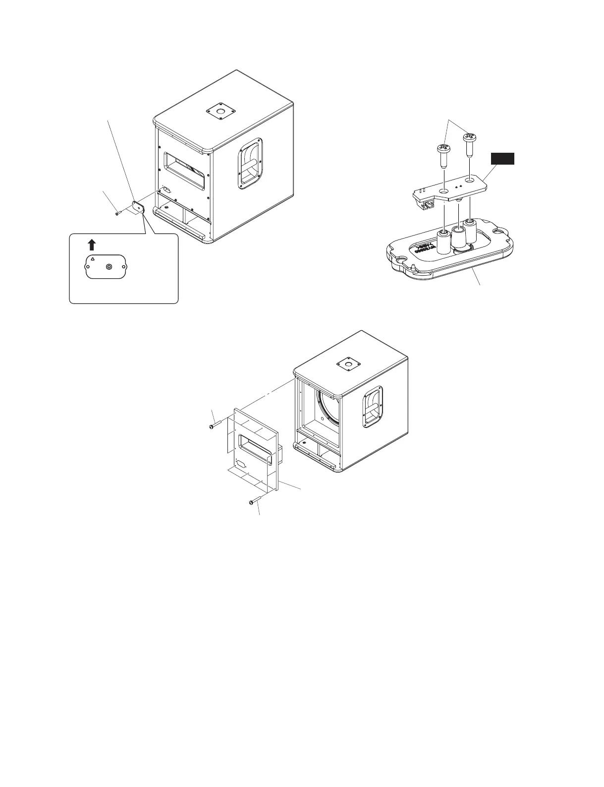
PORT BOARD ASSEMBLY
(ポート板 Assy)
※This figure shows the DXS12.
(この図は、DXS12です。)
833(56,'((上側)
&KHFNWKHGLUHFWLRQ
(上下方向を確認のこと。)
/('3$1(/$66(0%/<
(LEDパネル Assy)
>$@
※7KLVILJXUHVKRZVWKH';6
(この図は、DXS12です。)
Fig. A-2
(図A-2)
A-4. Speaker (Woofer)
(Time required: About 5 minutes)
A-4-1 Remove the metal grille assembly. (See procedure A-1.)
A-4-2 Remove the LED panel assembly.
(See procedure A-2-2.)
A-4-2 Remove the port board assembly. (See procedure A-3.)
A-4-3 Remove the eight (8) screws marked [40]. The speaker
(woofer) can then be removed. (Fig. A-5, Fig. A-6)
* When installing the speaker (woofer), fi rst tighten
the four (4) priority screws in order as shown in
Fig. A-5.
A-4-4 Remove the LFSPOUT connector assembly (red/black)
attached to the speaker (woofer) terminal.
(Fig. A-5, Fig. A-7)
* The speaker (woofer) is heavy. Be careful not to drop
it.
Fig. A-4
(図A-4)
/('
>@
O/('3$1(/$66(0%/<(LED パネル Assy)
/('3$1(/68%$66(0%/<
(LED パネル SUBAssy)
Fig. A-3
(図A-3)
A-4. スピーカ(ウーファー)
(所要時間:約 5 分)
A-4-1 メタルグリル Ass'y を外します。(A-1 項参照)
A-4-2 LED パネル Ass'y を外します。(A-2-2 項参照)
A-4-2 ポート板 Ass'y を外します。(A-3 項参照)
A-4-3 [40] のネジ 8 本を外して、スピーカ(ウーファー)
を外します。(図 A-5、図 A-6)
※ スピーカ(ウーファー)を取り付けるときは、優先ネジ
4 本を図に示す順番で先に締めてください。(図 A-5)
A-4-4 スピーカ(ウーファー)端子に取り付けられてい
る LFSPOUT 束線(赤/黒)を外します。
(図 A-5、図 A-7)
※ スピーカ(ウーファー)は重量がありますので、落下さ
せない様に注意してください。
 Loading...