39
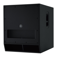
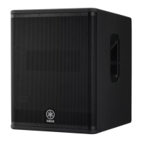
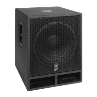
DXS12/DXS15
2. Inspection Items
2-1. Power consumption
Perform measurement with no signal input.
Confi rm that the primal power consumption is 30 W or less.
2-2. Adjustment of AMPSW Circuit Board
* The tip of the screwdriver for adjustment must be
insulation material.
(1) Adjustment of ±VB voltage
2 pin of CN104 is +VB voltage, 6 pin of CN104 is
-VB voltage, and of each into the jig tool.
The voltage between CN104 2 pin-CN104 6 pin is
measured.
VR101 is adjusted so that the voltage value between
CN104 2 pin-CN104 6 pin may become 110 V±1 V.
1-3. Preparation
• The load resistors for each output terminals are as
follows.
SP OUT (LF) Between 1 pin and 3 pin of CN609:
8 ohms±1 % (Rated 500 W or more)
• 0 dBu is referenced to 0.775 Vrms. 0 dBV is referenced
to 1 Vrms.
• Unless otherwise specifi ed, the controls should be set
as follows.
Level control (INPUT) : - ∞ (MIN)
POLARITY switch : NORM
LPF switch : 80 Hz
D-XSUB switch : OFF
FRONT LED DISABLE switch : OFF
• Unless otherwise specifi ed, the input signal should be
100 Hz sine wave.
• The output impedance of signal generator should be
100 Ω - 150 Ω.
1-4. Activating diagnostic mode and application for
service inspection
The inspection must be performed with both the
diagnostic mode of the unit and the application for service
inspection of PC are activated.
Follow the steps below.
(1) With the FRONT LED DISABLE switch turned off,
turn on the power to the amp assembly.
After about 4 seconds, the diagnostic mode is
activated and all LEDs on the rear panel blink at
intervals of 500 ms.
(2) Run application for service inspection (DiagDXS-
SERVICE.exe).
2. 検査項目
2-1. 消費電力
測定は入力無信号の状態で行います。
一次消費電力が 30W 以下であることを確認します。
2-2. AMPSW シートの調整
※ 調整用ドライバーは必ず先端が絶縁素材のもの
を使用すること。
(1)± VB電圧の調整
CN104 の 2 ピンを +VB 電圧、CN104の6ピンを
-VB 電圧として治具側に取り込み、CN1042 ピ
ン− CN1046 ピン間の電圧を計測します。
CN1042 ピン− CN1046 ピン間の電圧値が 110
V ± 1V になるように VR101 を調整します。
1-3. 準備
•
各出力端子に下記の負荷抵抗を接続します。
SPOUT(LF)CN6091‒3ピン間:
8Ω± 1%(定格 500W 以上)
• 0dBu=0.775Vrms、0dBV=1Vrms とします。
• 特に指定のない場合、コントロールツマミ類は以下の
ように設定します。
LEVEL コントロール(INPUT):– ∞(最小)
POLARITY スイッチ :NORM
LPF スイッチ :80Hz
D-XSUB スイッチ :OFF
FRONTLEDDISABLE スイッチ :OFF
• 特に指定のない場合、入力信号は 100Hz正弦波
とします。
• 信号発生器の出力インピーダンスは 100Ω〜 150
Ωとします。
1-4. ダイアグモードとサービス検査用アプリケーション
の起動
検査は、本体のダイアグモードと PCのサービス検
査用アプリケーション両方を起動した状態で行いま
す。
以下の操作をします。
(1)FRONTLEDDISABLE スイッチをオフにした状
態でアンプ Ass'y の電源を入れます。
約 4 秒後、ダイアグモードが起動し、リアパネ
ルにある全 LED が 500ms 間隔で点滅します。
(2)サービス検査用アプリケーション(DiagDXS-
SERVICE.exe)を起動します。
 Loading...