CIRCUIT DIAGRAM
(コネクタの接続について)2. Connection of connectors
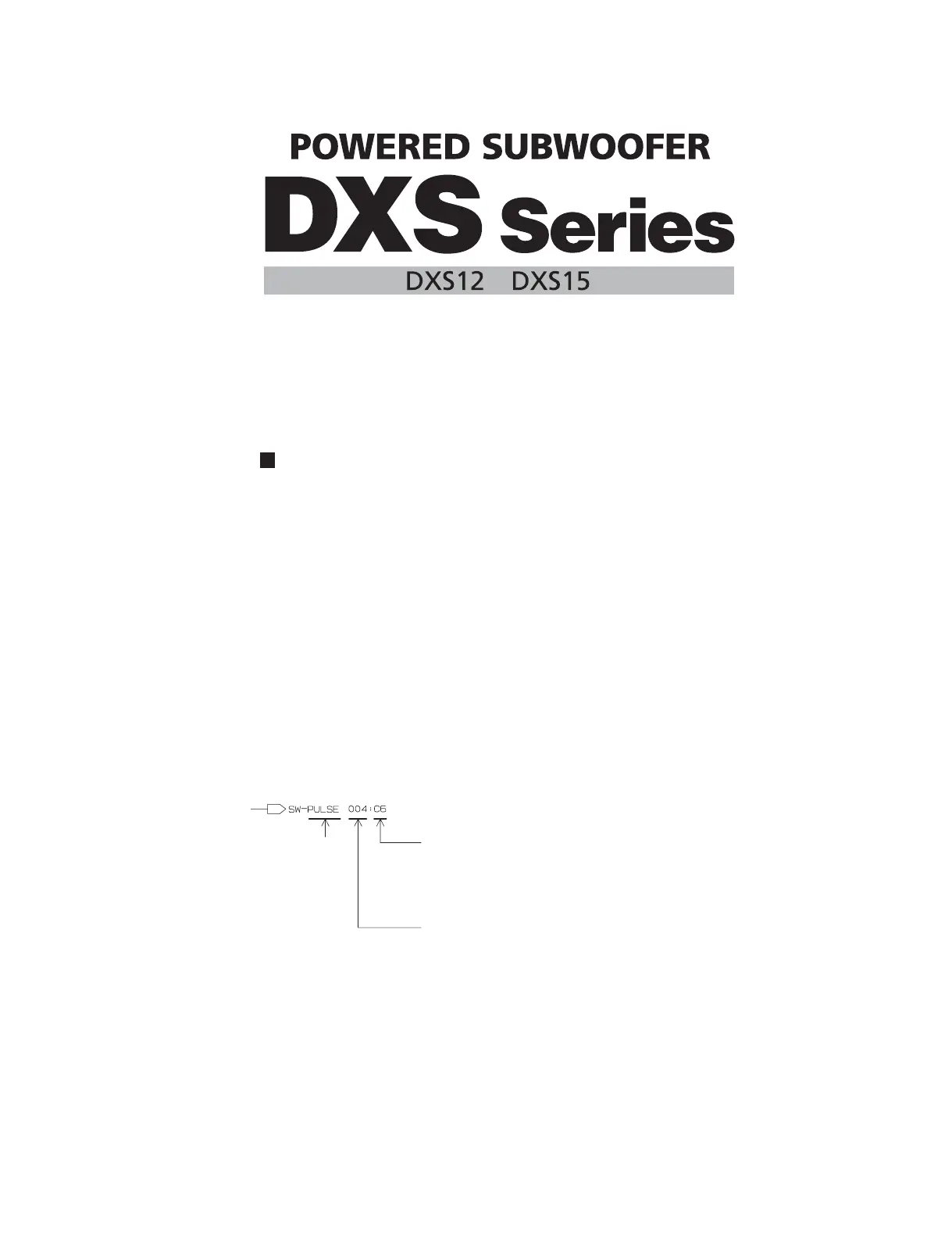
(Example)
to AMPSW - CN101
(Page 5: P-3)
(例)
toAMPSW-CN101
(Page5:P-3)
Page 5 are the page of a circuit diagram.
P-3 is indicates the location of the counter inter-sheet connector.
(The alphabet indicates horizontal direction and the number indicates
vertical direction)
Page5 は回路図のページです。[5 ページ ]
P-3 は対応するシート間コネクタのあるロケーションを示します。
(アルファベットが水平方向、数字が垂直方向)
BLOCK DIAGRAM(ブロックダイアグラム) ...........................3
LEVEL DIAGRAM(レベルダイアグラム) ................................4
CIRCUIT DIAGRAM(回路図)
AMPSW (001 – 004) ............................................................5–8
DSPW (001 – 002) .............................................................9–10
LED ........................................................................................12
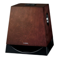
SUBW1 ..................................................................................11
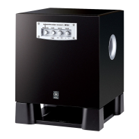
SUBW2 ..................................................................................12
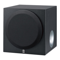
SUBW3 ..................................................................................12
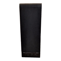
SUBW4 ..................................................................................12
CONTENTS(目次)
(シート間コネクタの読み方について)
(回路図表記上の注意)
Notation for Circuit Diagrams
1. How to identify inter-sheet connectors
(3桁の数字は信号の行先ページを示します。)
The 3-digit number indicates the destination page.
対応するシート間のコネクタのあるロケーションを示します。
(アルファベットが水平方向、数字が垂直方向)
This indicates the location of the counter inter-sheet connector.
(The alphabet indicates horizontal direction and the number
indicates vertical direction)
Signal name
(信号名)
 Loading...