Basic components
19
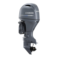
gine off. Attempting to use this switch
while the boat is moving could increase
the risk of falling overboard and could
distract the operator, increasing the risk
of collision with another boat or an obsta-
cle.
NOTE:
For instructions on using the power trim and
tilt switch, see page 38.
EMU26243
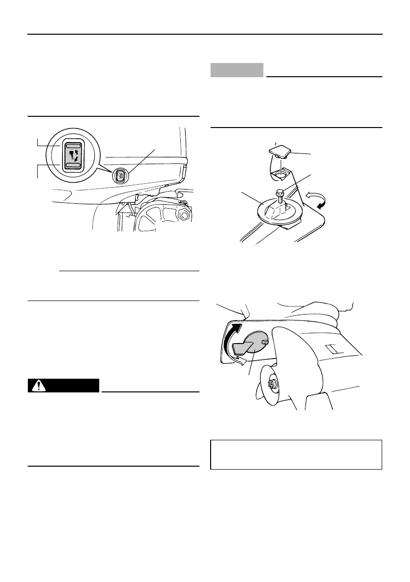
Trim tab with anode
The trim tab should be adjusted so that the
steering control can be turned to either the
right or left by applying the same amount of
force.
WARNING
EWM00840
An improperly adjusted trim tab could
cause difficult steering. Always test run
after the trim tab has been installed or re-
placed to be sure steering is correct. Be
sure you have tightened the bolt after ad-
justing the trim tab.
If the boat tends to veer to the left (port side),
turn the trim tab rear end to the port side “A”
in the figure. If the boat tends to veer to the
right (starboard side), turn the trim tab end to
the starboard side “B” in the figure.
CAUTION:
ECM00840
The trim tab also serves as an anode to
protect the engine from electrochemical
corrosion. Never paint the trim tab as it
will become ineffective as an anode.
EMU26341
Tilt support lever for power trim and
tilt model
To keep the outboard motor in the tilted up
position, lock the tilt support lever to the
1. Power trim and tilt switch
UP
DN
ZMU04223
1
1. Trim tab
2. Bolt
3. Cap
1. Trim tab
Bolt tightening torque:
42.0 Nm (31 ft-lb) (4.2 kgf-m)
1
2
3
ZMU02525
A
B
A
B
1
ZMU05048

 Loading...