 Loading...
Do you have a question about the Yamaha F100D and is the answer not in the manual?
| Brand | Yamaha |
|---|---|
| Model | F100D |
| Category | Outboard Motor |
| Language | English |
Guide for effective service using manual format and symbols.
Explanation of symbols for data, lubricants, and sealants.
Procedures to prevent accidents, injury, and ensure quality service.
Information on applicable models, codes, and serial numbers.
Guidance on choosing a propeller to optimize performance and engine life.
Essential checks for a smooth delivery process and efficient operation.
Detailed specifications including dimensions, weight, and performance for F80BET and F100DET models.
Specifications for engine components like power unit, cylinder head, and valves.
Specified torque values for various parts and assemblies in N·m, kgf·m, and ft·lb.
Tools required for periodic maintenance and adjustments.
Guidelines for routine maintenance intervals based on operating hours and time.
Procedures for checking and adjusting the top cowling fit.
Checks for fuel hoses, joints, and fuel filters.
Procedures for checking engine oil, timing belt, spark plugs, thermostat, and cooling passage.
Checks and adjustments for engine idle speed and throttle linkage.
Checks for power trim and tilt operation and fluid level.
Procedures for checking and changing gear oil and inspecting the lower unit for air leakage.
Checks for anodes, battery, and lubrication points.
Tools specific to fuel system diagnostics and service.
Diagram showing the routing of fuel and blowby hoses.
Procedures for checking, disassembling, and assembling the fuel filter and pump.
Checks and installation of throttle position sensor and idle speed control.
Procedures for reducing fuel pressure, measuring it, and disassembling/assembling the vapor separator.
Procedure for checking the canister for cracks and leaks.
Tools for power unit maintenance, including compression and valve train checks.
Checks for compression pressure, oil pressure, and valve clearance.
Information on the throttle linkage system.
Information on the Engine Control Module.
Details about the junction box components.
Procedures for removing, checking, and installing cylinder head components.
Procedures for removing, checking, and installing the exhaust cover and pressure control valve.
Procedures for disassembling, checking, and assembling the cylinder block.
Tools required for servicing the lower unit components.
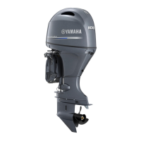
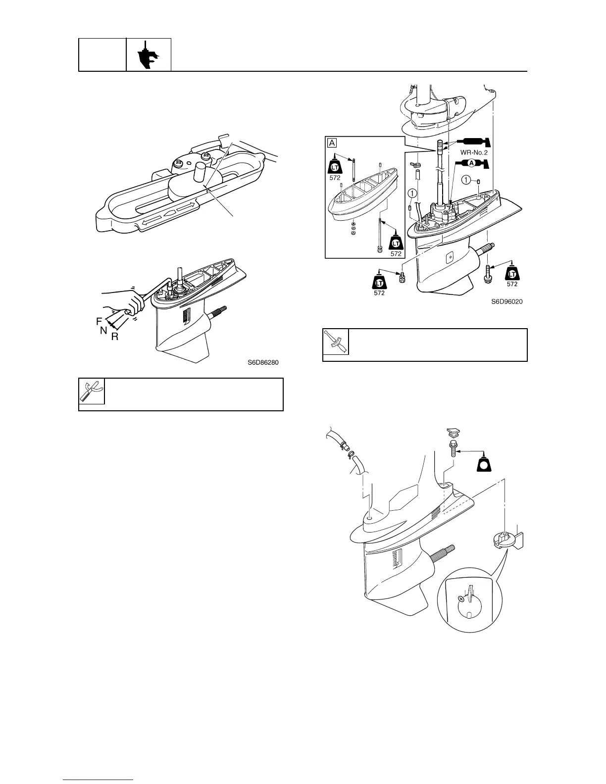
Procedures for removing, disassembling, and assembling the lower unit.
Procedures for removing, disassembling, and assembling the propeller shaft housing.
Procedures for removing, disassembling, and assembling the drive shaft and lower case.
Procedures for selecting and installing shims for pinion and forward gears.
Procedure for measuring and adjusting forward gear backlash.
Tools for servicing bracket unit components.
Exploded view and parts list for the shift rod assembly.
Exploded views and parts list for the bottom cowling components.
Procedures for removing, disassembling, and assembling the upper case.
Procedures for removing and installing the steering arm.
Procedures for removing, installing, and adjusting clamp brackets and trim sensor.
Procedures for removing and installing the power trim and tilt unit.
Procedures for disassembling, checking, and assembling the power trim and tilt motor.
Procedures for disassembling, checking, and assembling the gear pump.
Procedures for disassembling, checking, and assembling tilt and trim cylinders.
Checks for fuses, relays, switches, and trim sensors.
Tools for electrical system diagnostics.
Procedures for measuring peak voltage and low resistance.
Views showing the location of electrical components.
Checks for ignition spark, plug wires, coils, ECM, pulser coils, sensors, and relays.
Checks for injectors, electric fuel pump, and relays.
Checks for fuses and starter relay.
Procedures for disassembling, checking, and operating the starter motor.
Checks for stator coil and rectifier regulator.
Tools for troubleshooting, including the Yamaha Diagnostic System.
Introduction to the diagnostic system, its features, functions, and hardware requirements.
Troubleshooting chart for engine not cranking or starting.
Troubleshooting for power trim/tilt and shift mechanism issues.
Troubleshooting for battery drain and charging system issues.