6D93G11
7-46
1
2
3
4
5
6
7
8
9
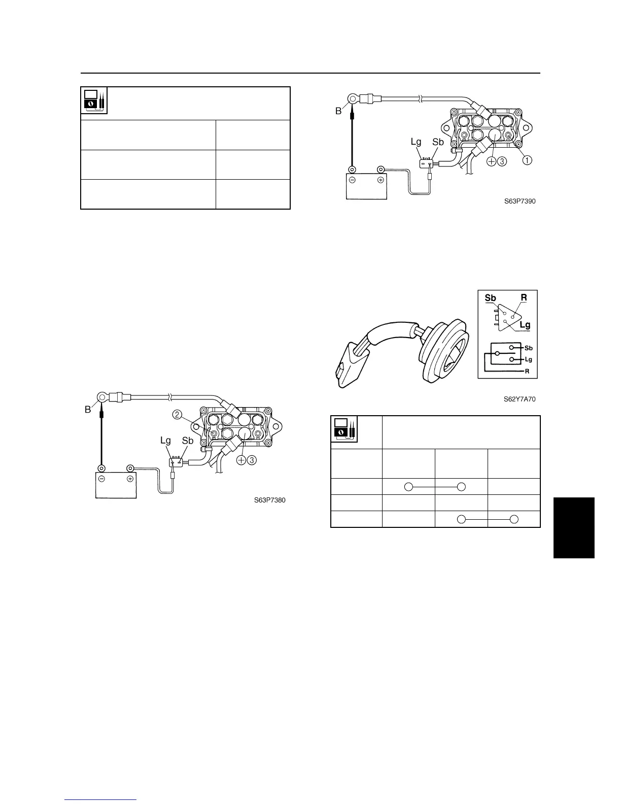
2. Connect the digital circuit tester between
power trim and tilt relay terminals
2
and
3
.
3. Connect the light green (Lg) lead to the
positive battery terminal and the black
(B) lead to the negative battery terminal
as shown.
4. Check for continuity between terminals
2
and
3
. Replace if there is no continu-
ity.
5. Connect the digital circuit tester between
power trim and tilt relay terminals
1
and
3
.
6. Connect the sky blue (Sb) lead to the
positive battery terminal and the black
(B) lead to the negative battery terminal
as shown.
7. Check for continuity between terminals
1
and
3
. Replace if there is no continu-
ity.
Checking the power trim and tilt
switch
1. Check the power trim and tilt switch for
continuity. Replace if out of specification.
Power trim and tilt relay continuity
Sky blue (Sb) – Black (B)
Light green (Lg) – Black (B)
Continuity
Terminal
1
– Terminal
4
Terminal
2
– Terminal
4
Continuity
Terminal
1
– Terminal
3
Terminal
2
– Terminal
3
No continuity
Lead color
Switch
position
Sky blue
(Sb)
Red (R)
Light green
(Lg)
Up
Free
Down
Tilt cylinder and trim cylinder / Power trim and tilt electrical system

 Loading...