6D93G11
5-12
1
2
3
4
5
6
7
8
9
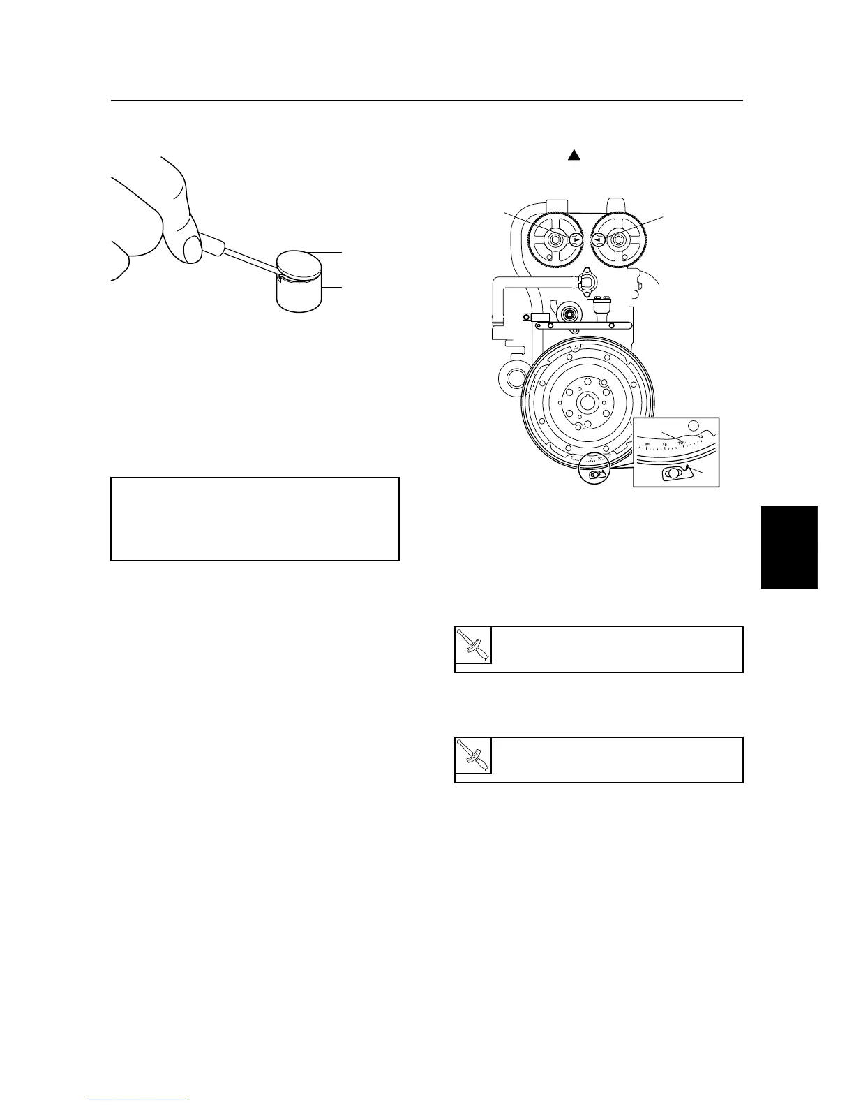
11. Remove the valve shim
C
from the valve
lifter
D
using a thin screwdriver.
12. Measure the valve shim thickness with a
micrometer, and then note the measure-
ment.
13. Select the necessary valve shim by cal-
culating its thickness with the following
formula.
Example:
If the “Removed valve shim thickness” is 2.10
mm, the “Measured valve clearance” is 0.30
mm and the “Specified valve clearance” is
0.20 mm, then the necessary valve shim
thickness = 2.10 + 0.30 – 0.20 = 2.20 mm
14. Install the necessary valve shim into the
valve lifter, and then install the valve lift-
ers into the cylinder head.
15. Install the camshafts, camshaft caps,
driven sprockets, and timing belt, and
then tighten the tensioner bolt.
16. Check the valve clearance. Adjust if nec-
essary.
17. Loosen the tensioner bolt, and then
remove the timing belt and driven sprock-
ets.
18. Install the cylinder head cover and driven
sprockets.
19. Check that the “TDC” mark
a
on the fly-
wheel magnet is aligned with the pointer
b
, and that “” marks
c
and
d
on the
driven sprockets are aligned.
20. Install the timing belt.
21. Install the spark plugs, and then connect
the spark plug wires, fuel hoses, and
blowby hose.
22. Install the spark plug wire cover, filter,
and flywheel magnet cover.
Necessary valve shim thickness =
Removed valve shim thickness +
Measured valve clearance – Specified
valve clearance
S6D85190
C
D

 Loading...