E
12
34
56
78
90
qw
er
ty
ui
op
as
df
GEN
INFO
A50001-1-4
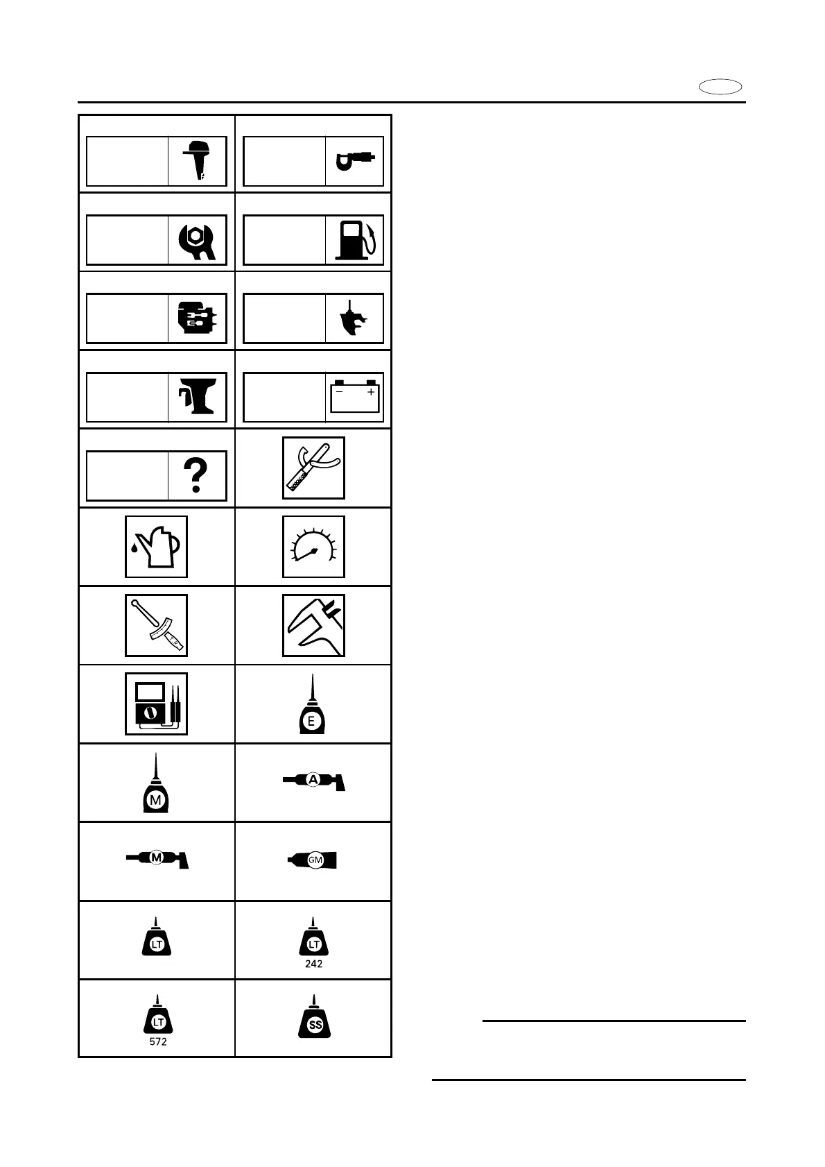
SYMBOLS
Symbols 1 to 9 are designed as thumb-
tabs to indicate the content of a chapter.
1 General Information
2 Specifications
3 Periodic Inspection and Adjustment
4 Fuel System
5 Power Unit
6 Lower Unit
7 Bracket Unit
8 Electrical System
9 Trouble-analysis
Symbols 0 to t indicate specific data:
0 Special Tool
q Specified liquid
w Specified engine speed
e Specified torque
r Specified measurement
t Specified electrical value
[Resistance (½), Voltage (V), Electric current
(A)]
Symbol y to o in an exploded diagram in-
dicate the grade of lubricant and location of
the lubrication point:
y Apply Yamaha 4-stroke outboard motor oil
u Apply molybdenum disulfide oil
i Apply water resistant grease (Yamaha
grease A, Yamaha marine grease)
o Apply molybdenum disulfide grease
Symbols p to f in an exploded diagram
indicate grade of sealing or locking agent,
and location of application point:
p Apply Gasket maker
®
a Apply LOCTITE
®
No. 271 (Red LOCTITE)
s Apply LOCTITE
®
No. 242 (Blue LOCTITE)
d Apply LOCTITE
®
No. 572
f Apply Silicon sealant
NOTE:
In this manual, the above symbols may not
be used in every case.
SPEC
INSP
ADJ
FUEL
POWR LOWR
BRKT ELEC
TRBL
ANLS
271

 Loading...