EasyManuals Logo
Home>Yamaha>Outboard Motor>F4A

Yamaha F4A Service Manual

Yamaha F4A
307 pages
To Next Page IconTo Next Page
To Previous Page IconTo Previous Page
Page #176 background imageLoading...
Page #176 background image
E
CRANKCASE AND CAMSHAFT
POWR
CRANKCASE AND CAMSHAFT
EXPLODED DIAGRAM
3
4
1
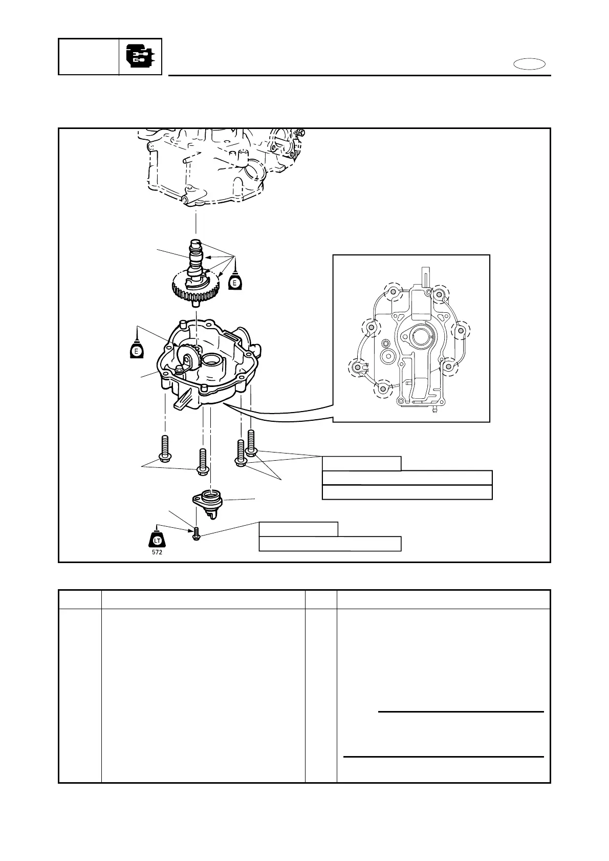
1st 10 Nm (1.0 m•kg, 7.2 ft•lb)
2nd 22 Nm (2.2 m•kg, 16 ft•lb)
18 Nm (1.8 m•kg, 13 ft•lb)
M8 x 50 mm
M8 x 20 mm
2
3
1
2
3
4
5
6
7
5
5-26
REMOVAL AND INSTALLATION CHART
Step
1
2
3
4
5
Q’ty
1
1
7
1
1
Service points
Follow the left “Step” for removal.
NOTE:
When installing the camshaft, the crank-
shaft ass’y must be fitted to the cylinder
body.
Reverse the removal steps for installation.
Procedure/Part name
CRANKCASE AND CAMSHAFT
REMOVAL
Bolt (oil seal housing)
Oil seal housing ass’y
Bolt with washer (crankcase)
Crankcase
Camshaft ass’y

Table of Contents

Other manuals for Yamaha F4A

Questions and Answers:

Question and Answer IconNeed help?

Do you have a question about the Yamaha F4A and is the answer not in the manual?

Yamaha F4A Specifications

General IconGeneral
BrandYamaha
ModelF4A
CategoryOutboard Motor
LanguageEnglish

Related product manuals