EasyManuals Logo
Home>Yamaha>Outboard Motor>F4A

Yamaha F4A Service Manual

Yamaha F4A
307 pages
To Next Page IconTo Next Page
To Previous Page IconTo Previous Page
Page #254 background imageLoading...
Page #254 background image
E
CARRYING HANDLE AND BOTTOM COWLING
BRKT
CARRYING HANDLE AND BOTTOM COWLING
EXPLODED DIAGRAM
8
10
9
6
7
2
2
4
3
5
M6 x 25 mm
M6 x 25 mm
M6 x 16 mm
M6 x 16 mm
15
13
15
11
14
12
1
a
b
a
7-1
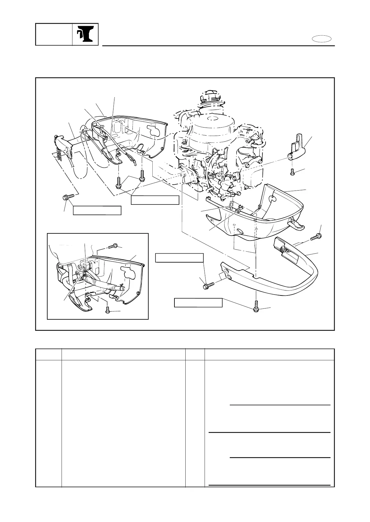
REMOVAL AND INSTALLATION CHART
Step
1
2
3
4
5
Q’ty
1
4
3
1
1
Service points
Follow the left ”Step” for removal.
Refer to ”INTAKE SYSTEM“ in chapter 4.
NOTE:
After installation, clamp the engine stop
switch lead to part 2 using the lead clamp
a.
NOTE:
Clamp the hi-tension cord using the cord
clamp b, after the bottom cowling 2 has
been fitted.
Procedure/Part name
CARRYING HANDLE AND
BOTTOM COWLING REMOVAL
Top cowling
Choke wire
Engine stop switch lead
Bolt with washer (carrying handle 2)
Bolt with washer (bottom cowling 2)
Carrying handle2 (protector)
Bottom cowling 2

Table of Contents

Other manuals for Yamaha F4A

Questions and Answers:

Question and Answer IconNeed help?

Do you have a question about the Yamaha F4A and is the answer not in the manual?

Yamaha F4A Specifications

General IconGeneral
BrandYamaha
ModelF4A
CategoryOutboard Motor
LanguageEnglish

Related product manuals