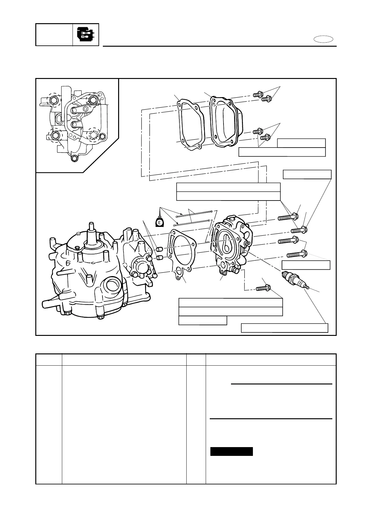
E
CYLINDER HEAD AND PUSH ROD
POWR
CYLINDER HEAD AND PUSH ROD
EXPLODED DIAGRAM
4
3
2
2
6
6
1
5
10
8
11
11 Nm (1.1 m•kg, 8.0 ft•lb)
25 Nm (2.5 m•kg, 18 ft•lb)
1st 6 Nm (0.6 m•kg, 4.3 ft•lb)
2nd 12 Nm (1.2 m•kg, 8.7 ft•lb)
2
4
3
1
1st 15 Nm (1.5 m•kg, 10.8 ft•lb)
2nd 30 Nm (3.0 m•kg, 22 ft•lb)
M6 x 12 mm
M8 x 60 mm
M8 x 40 mm
M6 x 45 mm
9
7
5-11
REMOVAL AND INSTALLATION CHART
Step
1
2
3
4
5
6
7
Q’ty
1
4
1
1
1
3
1
Service points
Follow the left “Step” for removal.
NOTE:
9Cylinder head maintenance is possible
with the power unit mounted.
9Loosen the locknut (rocker arm), to
install the cylinder head and push rod.
Not reusable
Procedure/Part name
CYLINDER HEAD AND PUSH ROD
REMOVAL
Spark plug
Bolt (cylinder head cover)
Cylinder head cover
Gasket (cylinder head cover)
Bolt (cylinder head)
Bolt (cylinder head)
Bolt (cylinder head)
 Loading...