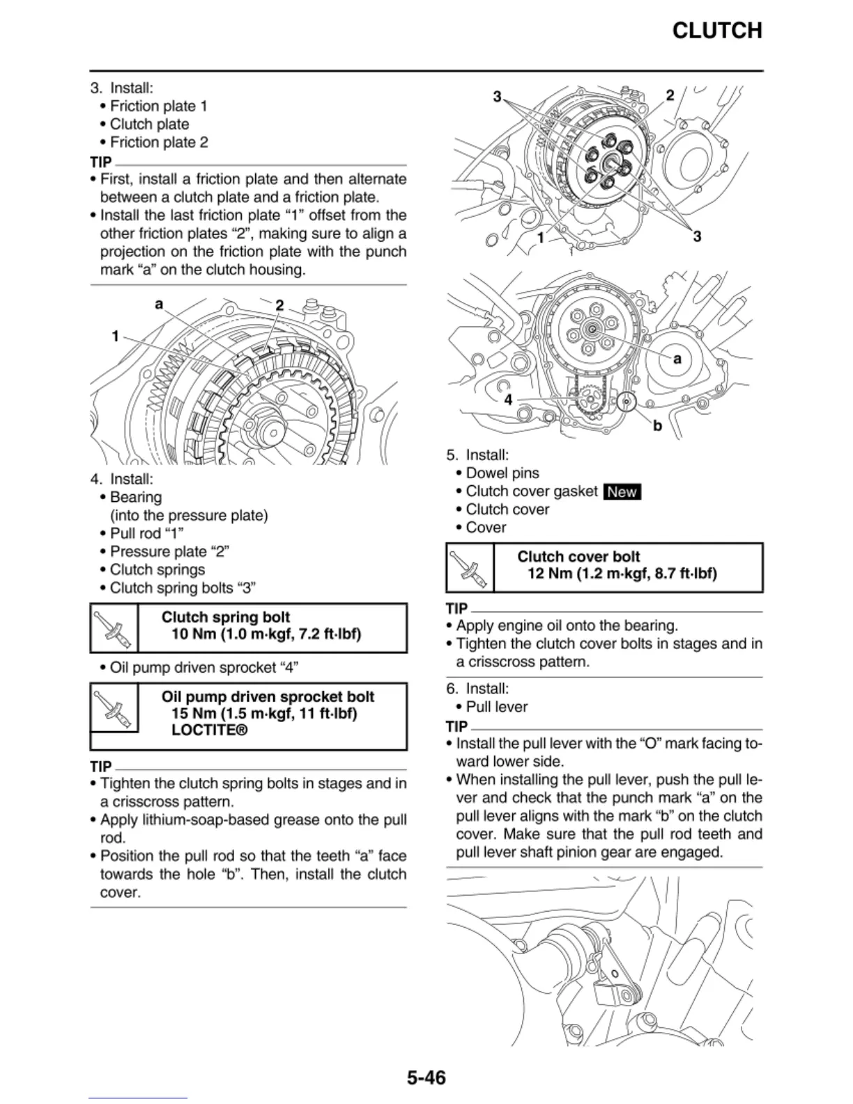
3. Install:
• Friction plate 1
• Clutch plate
• Friction plate 2
TIP
~~~~~~~~~~~~~~
• First, install a
fri
ction plate and then alternate
between a c
lu
tch plate and a friction plate.
• Install the last friction plate "1" offset from the
other friction plates
"2",
maki
ng
su
re
to align a
projection on t
he
fric
ti
on plate with the pu
nc
h
mark "a" on t
he
clutch housing.
4. Install:
• Bea
rin
g
(into the pressure plate)
• Pull rod "1"
• Pressure plate "2"
• Clutch springs
• Clutch spri
ng
bol
ts
"3"
Clutch
spring
bolt
10 Nm (1.0 m·
kgf
, 7.2 ft·lbf)
• Oil pump driven sprocket "4"
Oil
pump
driven
sprocket
bolt
15 Nm
(1
.5 m·
k,gf,
11
ft·lbf)
LOCTITE®
TIP
~~~~~~~~~~~~~~
• Tighten the clutch sp
ring
bol
ts
in stages and in
a crisscross pa
tt
ern.
• Apply li
thi
um-soap-based grease onto the pu
ll
rod.
•
Pos
ition the pu
ll
rod
so
that
th
e teeth "a" face
towards the
ho
le
"b".
Then, install the c
lu
tc
h
cover.
5.
Insta
ll
:
• Dowel pins
• Clut
ch
cover gasket
IH¥j
• Clut
ch
cover
• Cover
Clutch
cover
bolt
CLUTCH
12
Nm
(1.2 m·kgf, 8.7 ft·lbf)
TIP
~~~~~~~~~~~~~~-
• Ap
pl
y en
gi
ne oil onto the bea
ri
ng.
• Tighten the clut
ch
cover bol
ts
in stages and in
a crisscross pattern.
6.
Install:
•
Pu
ll
lever
TIP
~~~~~~~~~~~~~~
• Insta
ll
th
e pull lever with the "O" mark facing to-
ward lower side.
• When installing the pull lever, push the pull le-
ver and check that the punch mark "a" on the
pull lever aligns wi
th
the mark "b" on the clutch
cover. Make sure that the pull rod teeth and
pull lever shaft pinion gear are engaged.
5-46
 Loading...