RX-V357/HTR-5830
16
RX-V357/HTR-5830
9
9
B
A
0
0
8
0
Note:
When assembling the FUNCTION (1) P.C.B., be careful not to
bend the pin of the connectors (CB101 and CB244).
FUNCTION (1) P.C.B.
FUNCTION (9) P.C.B.
FUNCTION (4) P.C.B.
FUNCTION (8) P.C.B.
CB104
C
B
1
0
3
CB652
M
A
IN
(1
) P
.C
.B
.
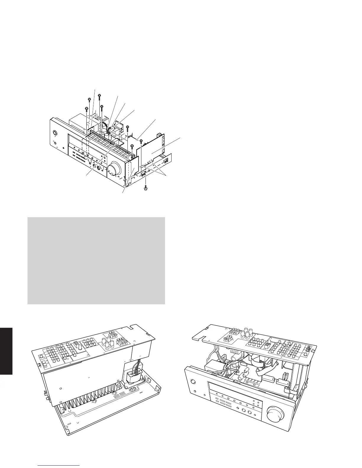
5. Removal of MAIN (1), FUNCTION (1), FUNCTION (8)
and FUNCTION (9) P.C.B.s
a. Remove 1 screw (8). (Fig. 5)
b. Remove FUNCTION (1) P.C.B. (Fig. 5)
c. Remove CB103, CB104 and CB652. (Fig. 5)
d. Remove 3 screws (9). (Fig. 5)
When checking the P.C.B.:
a. Remove the Top Cover.
b. Remove 3 screws (6). (Fig. 3)
c. Remove 1 screw (7). (Fig. 4)
d. Remove 3 screws (9). (Fig. 5)
e. Remove 4 screws (0). (Fig. 5)
f. Remove 1 screw (A). (Fig. 5)
g. Remove 1 screw (B ). (Fig. 5)
h. Place the P.C.B. upright. (Fig. A and B)
i. Be sure to connect the ground of MAIN (1) P.C.B.
(G103, G104, G241) and FUNCTION (4) P.C.B.
(G651) to the chassis with a jumper wire or the like.
Fig. A
Fig. 5
Fig. B
e. Remove 4 screws (0). (Fig. 5)
f. Remove MAIN (1), FUNCTION (4), FUNCTION (8) and
FUNCTION (9) P.C.B.s. (Fig. 5)
 Loading...