Home
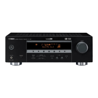
Yamaha
Receiver
RX-V357
Page 9 (REMOTE CONTROL PANELS)
Yamaha RX-V357 - REMOTE CONTROL PANELS
70 pages
Manual
Save Page as PDF
To Next Page
To Next Page
To Previous Page
To Previous Page
Loading...
RX-V357/HTR-5830
9
RX-V357/HTR-5830
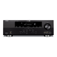
HTR-5830 (B, G, E models)
■
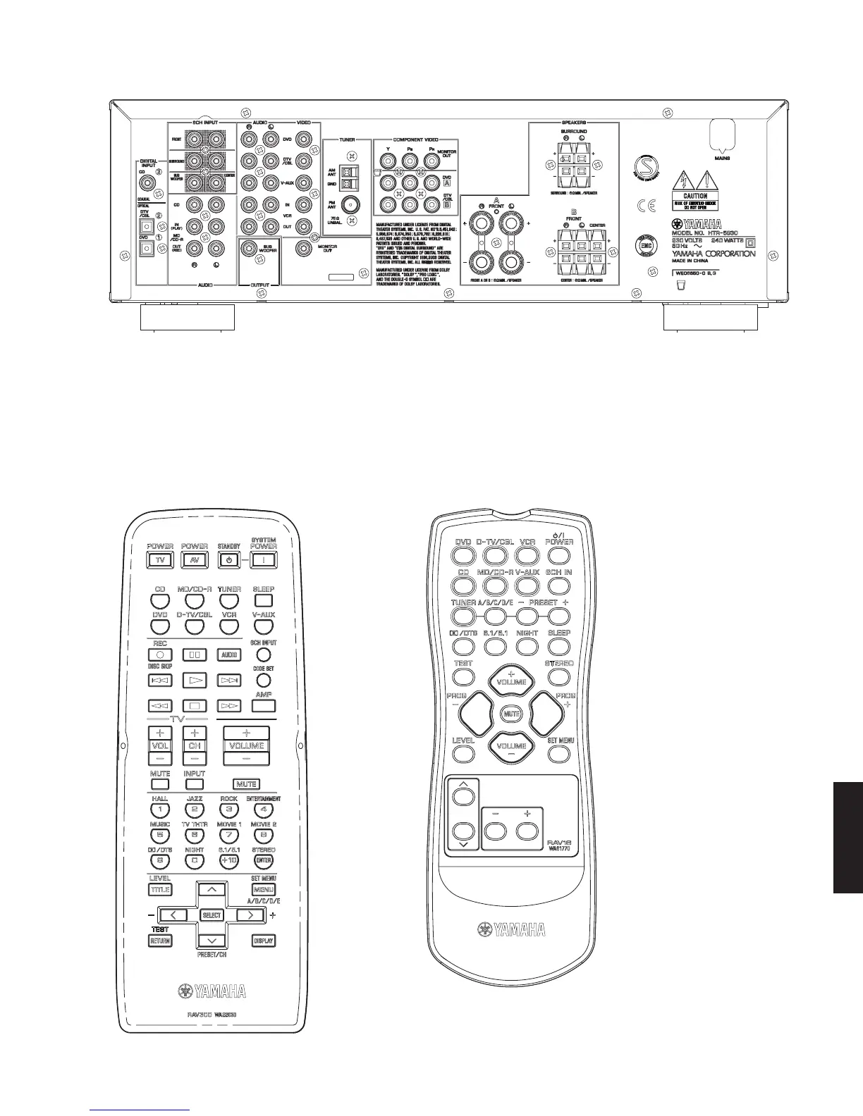
REMOTE CONTROL PANELS
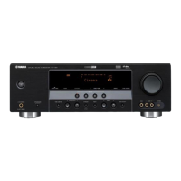
RX-V357 (C, R, T, K, A, L models)
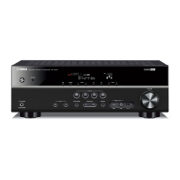
HTR-5830 (U, C, R, T, K, A models)
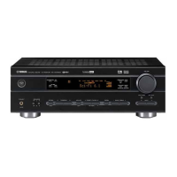
RX-V357 (B, G, E models)
HTR-5830 (B, G, E models)
8
10
Table of Contents
Main Page
Table of Contents
1
Service Manual
1
To Service Personnel
2
About Lead Free Solder
2
Impedance Selector
3
Front Panels
3
Rear Panels
5
Remote Control Panels
9
Specifications
10
The Variable Range of the Parameter (Min/Max/Step)
12
Set Menu Table
12
Resetting the Factory Presets
13
Changing Tuner’s FREQUENCY STEP
13
Removal of Top Cover
14
Removal of Front Panel Unit
14
Internal View
14
Disassembly Procedures
14
Removal of MAIN
15
Removal of DSP P.C.B.
15
When Checking the P.C.B.
16
Self Diagnosis Function (Diag)
17
Starting DIAG
19
Starting DIAG in the Protection Cancel Mode
19
Canceling DIAG
19
Display Provided When DIAG Started
19
Display During Menu Operation
20
Operation Procedure of DIAG Menu and SUB-MENU
20
Functions in DIAG Mode
20
Initial Settings Used to Start DIAG
20
YSS 0Db
21
Analog Bypass
21
Dsp through
21
Details of DIAG Menu
21
Yss Full Bit P
22
Ram through
23
RAM 0Db
23
Pro Logic
24
Speakers Set
25
HP Test
26
Other Input
26
External Decoder
26
Manual Test
27
Display Check
27
Factory Preset
28
Preset Inhibit
28
Preset Reserved
28
Preset Stations
28
Ad Data Check/Fan Test
29
DC/PS (Protection Detection)
29
Thm/Fan (Temperature Detection/Fan Drive Level)
29
IMP SW/POWER LIMIT (Impedance/Power Limiter Detection)
29
IF STATUS (Input Function Status)
30
Dsp Ram Check
31
MTT: Mute Trigger
31
YSS938 Bus Check
31
Pld / Sram Bus Check
31
Sd Dl Code
32
Soft Sw
32
Microprocessor Information
33
Confirmation of Idling Current of MAIN P. C. B.
34
Confirmation of Idling Current
34
Grid Assignment
35
Pin Connection
35
Display Data
35
Anode Connection
36
IC Data
37
Printed Circuit Board
43
Printed Circuit Board
45
Pin Connection Diagram
52
Block Diagram
53
Schematic Diagram
54
Abbreviations
59
Electrical Parts
59
Parts List
59
P.C.b. Dsp
60
P.C.b. Dsp & P.C.b. Function
60
P.C.b. Function
61
P.C.b. Main
65
Chip Parts
65
Exploded View
66
Mechanical Parts
67
Remote Control
68
REMOTE CONTROL RAV16 (B, G, E Models)
69
Parts List for Carbon Resistors
69
Other manuals for Yamaha RX-V357
Owner's Manual
59 pages
Related product manuals
Yamaha RX-V350
53 pages
Yamaha RX-V359
74 pages
Yamaha RX-V377
97 pages
Yamaha RX-V385
133 pages
Yamaha RX-V367
80 pages
Yamaha RX-V361
78 pages
Yamaha RX-V363
99 pages
Yamaha RX-V365
85 pages
Yamaha RX-V375
84 pages
Yamaha RX-V340
79 pages
Yamaha RX-V371
88 pages
Yamaha RX-V3900
226 pages