EasyManuals Logo

Yamaha RX-V357 Service Manual

Yamaha RX-V357
70 pages
To Next Page IconTo Next Page
To Previous Page IconTo Previous Page
Page #3 background imageLoading...
Page #3 background image
RX-V357/HTR-5830
3
RX-V357/HTR-5830
Among some types of lead free solder currently available,
it is recommended to use one of the following types for the
repair work.
• Sn + Ag + Cu (tin + silver + copper)
• Sn + Cu (tin + copper)
• Sn + Zn + Bi (tin + zinc + bismuth)
Caution:
1. As the melting point temperature of the lead free solder
is about 30°C to 40°C (50°F to 70°F) higher than that of
the lead solder, be sure to use a soldering iron suitable
to each solder.
2. If lead solder must be used, be sure to remove lead free
solder from each terminal section of the parts to be
replaced and from the area around it completely before
soldering, or make sure that the lead free solder and
lead solder melt together fully.
IMPEDANCE SELECTOR
U, C models
IMPEDANCE SELECTOR
WARNING:
Do not change the IMPEDANCE SELECTOR
switch setting while the power to this unit is
on, otherwise this unit may be damaged.
FRONT PANELS
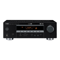
RX-V357 (C, R, T, K, A, L models)

Table of Contents

Other manuals for Yamaha RX-V357

Questions and Answers:

Question and Answer IconNeed help?

Do you have a question about the Yamaha RX-V357 and is the answer not in the manual?

Yamaha RX-V357 Specifications

General IconGeneral
Signal-To-Noise Ratio100 dB
Input Sensitivity200 mV
Tuner BandsAM/FM
Preset Station Qty40
Frequency Response10Hz - 100kHz
Outputs1 x headphones, 1 x subwoofer output
Input Impedance47 kohms
Audio D/A Converter24-bit / 192kHz
Built-in DecodersDolby Digital, DTS
Surround Sound EffectsDolby Pro Logic II
Sound EffectsCinema DSP
Tuning RangeAM: 530 - 1710 kHz, FM: 87.5 - 108 MHz
Power Output100 Watt

Related product manuals