Home
Yamaha
Boat
VX110 Sport
Yamaha VX110 Sport User Manual
4
of 1
of 1 rating
347 pages
Give review
Manual
Specs
To Next Page
To Next Page
To Previous Page
To Previous Page
6-8
E
JET
PUMP
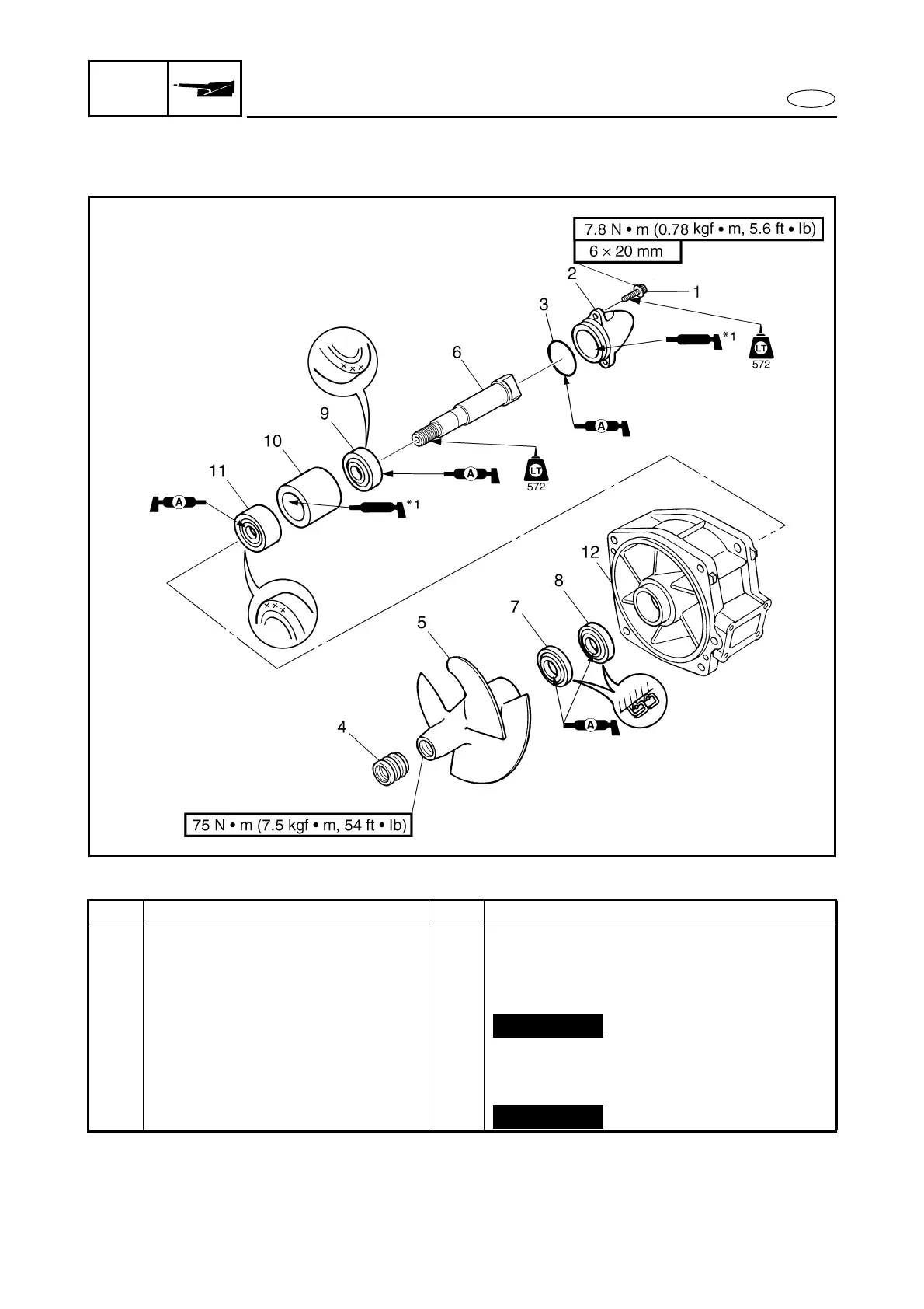
IMPELLER DUCT AND DRIVE SHAFT
IMPELLER DUCT AND DRIVE SHAFT
EXPLODED DIAGRAM
REMOVAL AND INSTALLATION CHART
*1: EPNOC grease AP #0
Step
Procedure/Part name
Q
’
ty
Service points
IMPELLER DUCT AND DRIVE
SHAFT DISASSEMBLY
Follow the left
“
Step
”
for disassembly.
1B
o
l
t
3
2C
a
p
1
3
O-ring
1
4C
a
p
1
5
Impeller
1
6
Drive shaft
1
7
Oil seal
1
Not reusable
Not reusable
206
208
Table of Contents
Table of Contents
9
Default Chapter
2
Lit-18616
2
Specifications
2
How to Use this Manual
3
Current:
6
Periodic Inspection and
6
Table of Contents
9
Chapter 1
10
Engine Serial Number
10
HULL IDENTIFICATION NUMBER (H.l.n.)
10
Identification Numbers
10
Jet Pump Unit Serial Number
10
PRIMARY L.D. NUMBER
10
Fire Prevention
11
Parts, Lubricants, and Sealants
11
Safety While Working
11
Self-Protection
11
Ventilation
11
Good Working Practices
12
Disassembly and Assembly
13
Special Service Tools
14
Measuring
14
Removal and Installation
16
Table of Contents
21
Chapter 2
23
General Specifications
23
Maintenance Specifications
24
Engine
24
Hull and Hood
27
Jet Pump Unit
27
Current:
28
Electrical
28
Tightening Torques
31
Fuel System
31
Specified Torques
31
General Torque
36
Cable and Hose Routing
37
Insp Adj
49
Chapter 3
50
Maintenance Interval Chart
50
Periodic Service
51
Control System
51
Steering Cable Inspection and Adjustment
51
Steering Column Inspection
51
Throttle Cable Inspection and Adjustment
53
Shift Cable Inspection and Adjustment (Deluxe Model Only)
54
Trolling Speed Inspection
55
Fuel Line Inspection
56
Fuel System
56
Power Unit
57
Valve Clearance Adjustment
57
Water Separator Inspection
57
Current:
63
Engine Oil Level Check
63
Engine Oil Change - Using Oil Changer
65
Air Filter Element Clean
67
Spark Plug Inspection
69
Battery Inspection
71
Electrical
71
Impeller Inspection
74
Jet Pump Unit
74
Water Inlet Strainer Inspection
74
Bilge Pump
75
Bilge Strainer Inspection
75
Drain Plug Inspection
75
General
75
Lubrication Points
75
Table of Contents
77
Chapter 4
78
Exploded Diagram
78
Fuel Tank and Fuel Pump Module
78
Removal and Installation Chart
78
Service Points
81
Check Valve Inspection
81
Fuel Hose Disconnection
81
Fuel Pump Module Removal
81
Fuel Hose Inspection
82
Fuel Pump Filter Inspection
82
Fuel Sender Inspection
82
Fuel Tank Inspection
82
Fuel Hose Connect
83
Fuel Pump Module Installation
83
Fuel Injection System
84
Exploded Diagram
84
Removal and Installation Chart
84
Throttle Body Assembly and Intake Manifold
87
Exploded Diagram
87
Removal and Installation Chart
87
Electrical System
89
Fuel Hose Clamps Removal
89
Fuel Hose Disconnection
89
Hose Clamps Installation
89
Service Points
89
Fuel Line Inspection
90
Fuel Hose Connection
91
Fuel Hose Installation (Replacing with New Fuel Hose)
91
Accelerator Position Sensor Inspection
92
Fuel Injectors Inspection
92
Throttle Body Assembly Inspection
92
Intake Assembly Installation
93
Air Filter Case Assembly Installation
94
Fuel Pressure Measurement
94
Table of Contents
97
Chapter 5
100
Engine Unit
100
Exploded Diagram
100
Removal and Installation Chart
100
Service Points
103
Compression Pressure Measurement
103
Engine Mount Inspection
105
Engine Unit Removal
105
Shim Removal
105
Coupling Clearance Inspection
106
Exhaust Pipes 1 and 2
107
Exploded Diagram
107
Removal and Installation Chart
107
Exhaust Manifold
110
Exploded Diagram
110
Removal and Installation Chart
110
Oil Tank
111
Exploded Diagram
111
Oil Tank Removal
111
Removal and Installation Chart
111
Service Points
111
Oil Strainer Inspection
117
Oil Tank Installation
117
Oil Pump
120
Exploded Diagram
120
Removal and Installation Chart
120
Oil Pump Installation
122
Oil Strainer Inspection
122
Service Points
122
Reduction Drive Gear
123
Exploded Diagram
123
Removal and Installation Chart
123
Bearing Removal
127
Drive Coupling Removal
127
Drive Shaft Removal
127
Service Points
127
Drive Shaft Inspection
128
Oil Pump Drive Shaft Inspection
128
Bearing Installing
129
Drive Coupling Installation
131
Drive Shaft Installation
131
Generator and Starter Motor
132
Exploded Diagram
132
Removal and Installation Chart
132
Flywheel Magneto Removal
137
Service Points
137
Starter Clutch Inspection
137
Flywheel Magneto Installation
139
Camshafts
140
Exploded Diagram
140
Camshaft Removal
142
Removal and Installation Chart
142
Service Points
142
Camshaft Inspection
146
Camshaft Sprockets Inspection
148
Timing Chain Tensioner Inspection
148
Camshaft Installation
149
Cylinder Head
153
Cylinder Head Removal
153
Exploded Diagram
153
Removal and Installation Chart
153
Cylinder Head Inspection
155
Cylinder Head Installation
156
Exploded Diagram
158
Removal and Installation Chart
158
Valve Removal
160
Valve Inspection
161
Valve Spring Inspection
161
Valve Guide Inspection
163
Valve Guide Replacement
163
Valve Seat Inspection
165
Valve Seat Reface
166
Valve Installation
168
Crankcase
170
Exploded Diagram
170
Removal and Installation Chart
170
Crankcase Disassembly
174
Service Points
174
Crankcase Inspection
175
Timing Chain Inspection
175
Crankcase Assembly
176
Connecting Rods and Pistons
179
Removal and Installation Chart
179
Connecting Rod and Piston Removal
181
Service Points
181
Cylinder and Piston Inspection
182
Piston Ring Inspection
183
Piston Pin Inspection
185
Connecting Rod Inspection
186
Connecting Rod and Piston Installation
188
Crankshaft
192
Exploded Diagram
192
Removal and Installation Chart
192
Crankshaft Inspection
193
Crankshaft Removal
193
Service Points
193
Crankshaft Installation
196
Cooling Water Hose
197
Exploded Diagram
197
Removal and Installation Chart
197
Pump Chapter 6 Jet Pump Unit
199
Chapter 6
201
Intake Grate and Ride Plate
201
Exploded Diagram
201
Removal and Installation Chart
202
Jet Pump Unit
202
Reverse Gate (Deluxe Model Only)
204
Exploded Diagram
204
Removal and Installation Chart
204
Jet Thrust Nozzle, Impeller Duct, and Impeller Housing 1
205
Exploded Diagram
205
Removal and Installation Chart
205
Impeller Duct and Drive Shaft
207
Drive Shaft Removal
209
Service Points
209
Drive Shaft Inspection
210
Impeller Inspection
210
Drive Shaft Installation
211
Transom Plate and Hoses
214
Bilge Hose Inspection
216
Bilge Strainer Inspection
216
Cooling Water Hose Inspection
216
Service Points
216
Bearing Housing
217
Removal and Installation Chart
218
Driven Coupling Removal and Installation
220
Intermediate Drive Shaft Removal
220
Service Points
220
Bearing and Intermediate Drive Shaft Inspection
221
Bearing Removal
221
Driven Coupling Inspection
221
Bearing and Oil Seals Installation
222
Intermediate Drive Shaft Installation
223
Table of Contents
225
Chapter 7
228
Electrical Components
228
Fuse Box
229
Exploded Diagram
229
Removal and Installation Chart
229
Exploded Diagram
230
Removal and Installation Chart
234
Electrical Analysis
236
Digital Tester
236
Inspection
236
Low Resistance Measurement
237
Peak Voltage Measurement
237
Peak Voltage Adapter
238
Test Harness
238
Ignition System
239
Wiring Diagram
239
Ignition Spark
241
Ignition System Peak Voltage
242
Battery
244
Fuse
244
Spark Plugs
244
Engine Stop Switch
245
Ignition Coil
245
Engine Temperature Sensor
246
Sensor Assembly
246
Thermoswitch (Engine)
247
Thermoswitch (Exhaust)
248
Main and Fuel Pump Relay
249
Electronic Control Throttle Valve Relay
250
Throttle Position Sensor
251
Accelerator Position Sensor
253
Cam Position Sensor
256
Slant Detection Switch
257
Fuel Control System
258
Wiring Diagram
258
Electric Fuel Pump
260
Fuel Sender
260
Accelerator Position Sensor
261
Fuel Injector
261
Main and Fuel Pump Relay
261
Oil Pressure Switch
261
Remote Control Unit (Deluxe Model Only)
261
Slant Detection Switch
261
Thermoswitch (Engine)
261
Thermoswitch (Exhaust)
261
Throttle Position Sensor
261
Starting System
262
Wiring Diagram
262
Battery
264
Fuses
264
Start Switch
264
Wiring Connections
264
Accelerator Position Sensor
265
Remote Control Unit (Deluxe Model Only)
265
Starter Relay
265
Throttle Position Sensor
265
Starter Motor
266
Armature Inspection
268
Service Points
268
Brush Holder Inspection
269
Starter Motor Front Cover Inspection
269
Charging System
270
Wiring Diagram
270
Battery
271
Fuse
271
Lighting Coil
271
Rectifier/Regulator
271
Off Throttle Steering System
272
Wiring Diagram
272
Accelerator Position Sensor
274
Ecm
274
Pickup Coil
274
Steering Sensor
274
Throttle Position Sensor
274
Indication System
275
Wiring Diagram
275
Battery
277
Buzzer
277
Ecm
277
Engine Temperature Sensor
277
Fuse
277
Main and Fuel Pump Relay
277
Remote Control Unit (Deluxe Model Only)
277
Thermoswitch (Engine)
277
Thermoswitch (Exhaust)
277
Multifunction Meter
278
Multifunction Meter Removal
278
Oil Pressure Switch
278
Display Function (Sport Model Only)
279
Display Function (Deluxe Model Only)
280
Speedometer Display
281
Fuel Level Meter Display and Fuel Warning Indicator
282
Hour Meter Display
282
Low Oil Pressure Warning Indicator
282
Tachometer Display
282
Voltage Meter Display
282
Check Engine Warning Indicator
283
Overheat Warning Indicator
283
Diagnostic Display
284
Remote Control System (Deluxe Model Only)
285
Remote Control System
285
Wiring Diagram
285
Low-Rpm Mode Indicator
286
Yamaha Security System Indicator
286
Checking the Remote Control Transmitter
287
Transmitter Registration
289
Replacing of the Transmitter Battery
290
Hull Hood Chapter 8 Hull and Hood
292
Default Chapter
294
Handlebar
294
Service Points
299
Chapter 8
299
Handlebar Assembly Installation
299
Handlebar Inspection
299
Handlebar Switch Inspection
299
Service Points
303
Rivet Installation
303
Engine Hatch Cover
304
Exploded Diagram
304
Removal and Installation Chart
304
Damper Stopper Inspection (Deluxe Model Only)
306
Service Points
306
Exploded Diagram
307
Removal and Installation Chart
307
Glove Compartment Assembly Installation
308
Service Points
308
Shift Lever (Deluxe Model Only)
309
Exploded Diagram
309
Removal and Installation Chart
309
Hoses
310
Exploded Diagram
310
Removal and Installation Chart
310
Cooling Water Pilot Outlet Installation
312
Grommet Installation
312
Service Points
312
Ventilation Hose Assembly Installation
312
Steering Column
313
Exploded Diagram
313
Removal and Installation Chart
313
Service Points
315
Steering Column Inspection
315
Hull Hood
315
Remote Control Cables and Speed Sensor Lead
316
Exploded Diagram
316
Removal and Installation Chart
316
Remote Control Cables Inspection
319
Service Points
319
Steering Cable (Jet Pump End) Installation
319
Steering Cable Stopper Installation
319
Remote Control Cables Adjustment
320
Shift Cable (Jet Pump End) Installation (Deluxe Model Only)
320
Shift Cable (Shift Lever End) Installation (Deluxe Model Only)
320
Seat and Hand Grip
321
Exploded Diagram
321
Removal and Installation Chart
321
Seat Lock Assembly Inspection
323
Service Points
323
Exhaust System
324
Exploded Diagram
324
Removal and Installation Chart
324
Exhaust Component Parts Sub-Assembly
327
Exhaust System Inspection
327
Service Points
327
Operating
336
Chapter 9 Connecting the Communication Cable to the Watercraft
336
Top View
336
Trouble Analysis
337
Trouble Analysis Chart
337
Self-Diagnosis
341
4
Based on 1 rating
Ask a question
Give review
Questions and Answers:
Need help?
Do you have a question about the Yamaha VX110 Sport and is the answer not in the manual?
Ask a question
Yamaha VX110 Sport Specifications
General
Displacement
1052cc
Type
Personal Watercraft
Width
46.1 inches
Seating Capacity
2
Engine Type
4-stroke, 4-cylinder
Related product manuals
Yamaha WaveRunner VX110 Sport
26 pages
Yamaha WaveRunner VX110 Deluxe
26 pages
Yamaha VX1100-J
106 pages
Yamaha VX1100B-J
106 pages
Yamaha VX1100A-J
106 pages
Yamaha VX110Sport
133 pages
Yamaha Waverunner VXS VX1800
318 pages
Yamaha WaveRunner VXR VX1800A
318 pages
Yamaha VXS
28 pages
Yamaha VX Cruiser
1 page
Yamaha VX/VX Sport
102 pages
Yamaha WaveRunner VX 700
181 pages