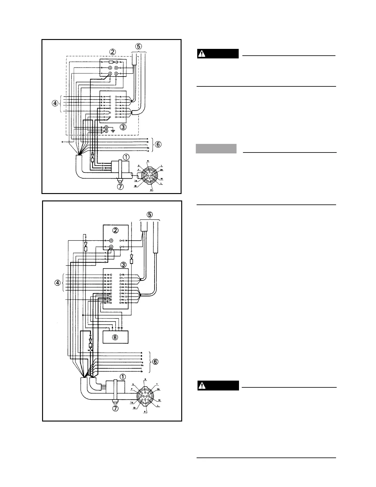
1 Adapter 6 To starter relay and
2 Rectifier-regulator PTT relay
3 CDI unit 7 Clamp
4 To ignition coil 8 Control unit
5 To flywheel magneto
10A-35
ADAPTER
This adapter is required for older Yamaha
outboards. Refer to the “Applicable
Models” section for details.
Installation instructions:
1) Remove the top cowling and remove the
cover from the CDI unit on the outboard
motor.
2) Remove the white wire on the CDI from
the main harness.
On V-6 models (except V6 EXCEL), do not
remove the white wire located beneath the
CDI unit that connects the CDI to the con-
trol unit. This is the wrong white wire. The
shift cut system will not function if this wire
is used.
3) Cut the eye terminal from the end of the
white wire and install a male bullet con-
nector.
4) Connect the adapter wires as follows:
• White wire to the white wire with the new
buller connector.
• White/black wire to the CDI terminal that
the white wire was removed from.
• Red wire to the red wire terminal of the
rectifier regulator
• Black wire to the black wire terminal of
the CDI.
5) Change the grommet for the black wire
from a 1-hole to a 2-hole type.
6) Clamp the adapter to the main wire har-
ness with a tie clamp.
7) Reinstall the CDI cover and the cowling.
8) Start the engine and make sure that it can
be stopped by the main switch, by the stop
switch, and by pulling the engine stop
switch lanyard.
The adapter must be connected correctly.
Be sure the main switch, engine stop
switch, and the engine stop switch lanyard
to stop the engine properly. Ensure that all
electrical connections are tight and will not
vibrate loose during normal operation.
Otherwise, the engine may not stop, which
could result in an accident.
 Loading...