iii
About this Manual
This manual describes procedures required for installation, wiring, and connecting
DC power input Σ-V Series servo drives, including a JOG operation for servomotors
not connected to machinery.
Be sure to refer to this manual and perform setup operations correctly.
Keep this manual in a location where it can be accessed for reference whenever
required.
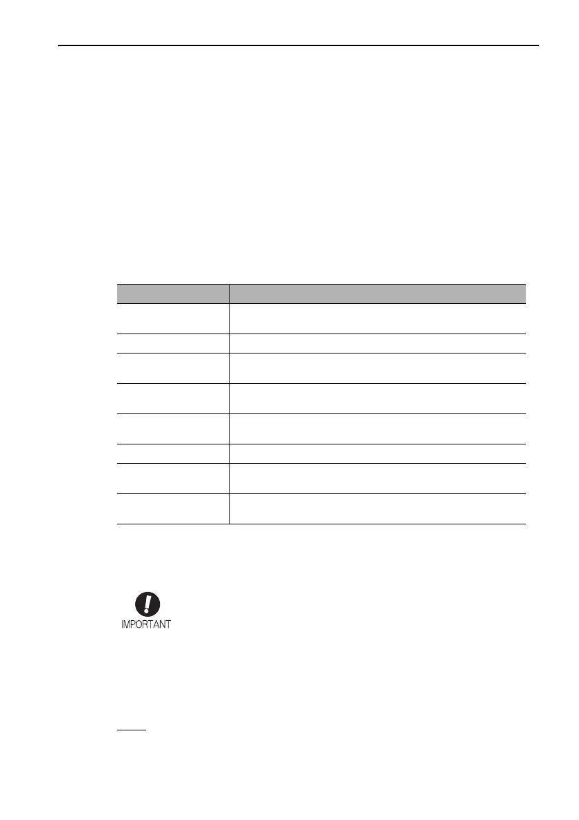
Description of Technical Terms
The following table shows the meanings of terms used in this manual.
Important Explanations
The following icon is displayed for explanations requiring special attention.
Notation Used in this Manual
In this manual, the names of reverse signals (ones that are valid when low) are written
with a forward slash (/) before the signal name, as shown in the following example:
Example
S-ON
= /S-ON
Ter m Meaning
Servomotor
Σ-7mini Series SGM7M servomotor
Σ-Vmini Series SGMMV servomotor
SERVOPACK DC power input Σ-V Series SGDV SERVOPACK
Servo Drive
A set including a servomotor and a SERVOPACK (i.e., a servo
amplifier)
Servo System
A servo control system that includes the combination of a servo
drive with a host controller and peripheral devices
Analog voltage
model
Analog voltage reference is used for the SERVOPACK interface.
Pulse train model Pulse train reference is used for the SERVOPACK interface.
M-II model
MECHATROLINK-II communications reference is used for the
SERVOPACK interface.
M-III model
MECHATROLINK-III communications reference is used for the
SERVOPACK interface.
• Indicates important information that should be memorized, as well as
precautions, such as alarm displays, that do not involve potential damage
to equipment.
 Loading...


