3.2 System Configuration Diagram
3-3
3.2 System Configuration Diagram
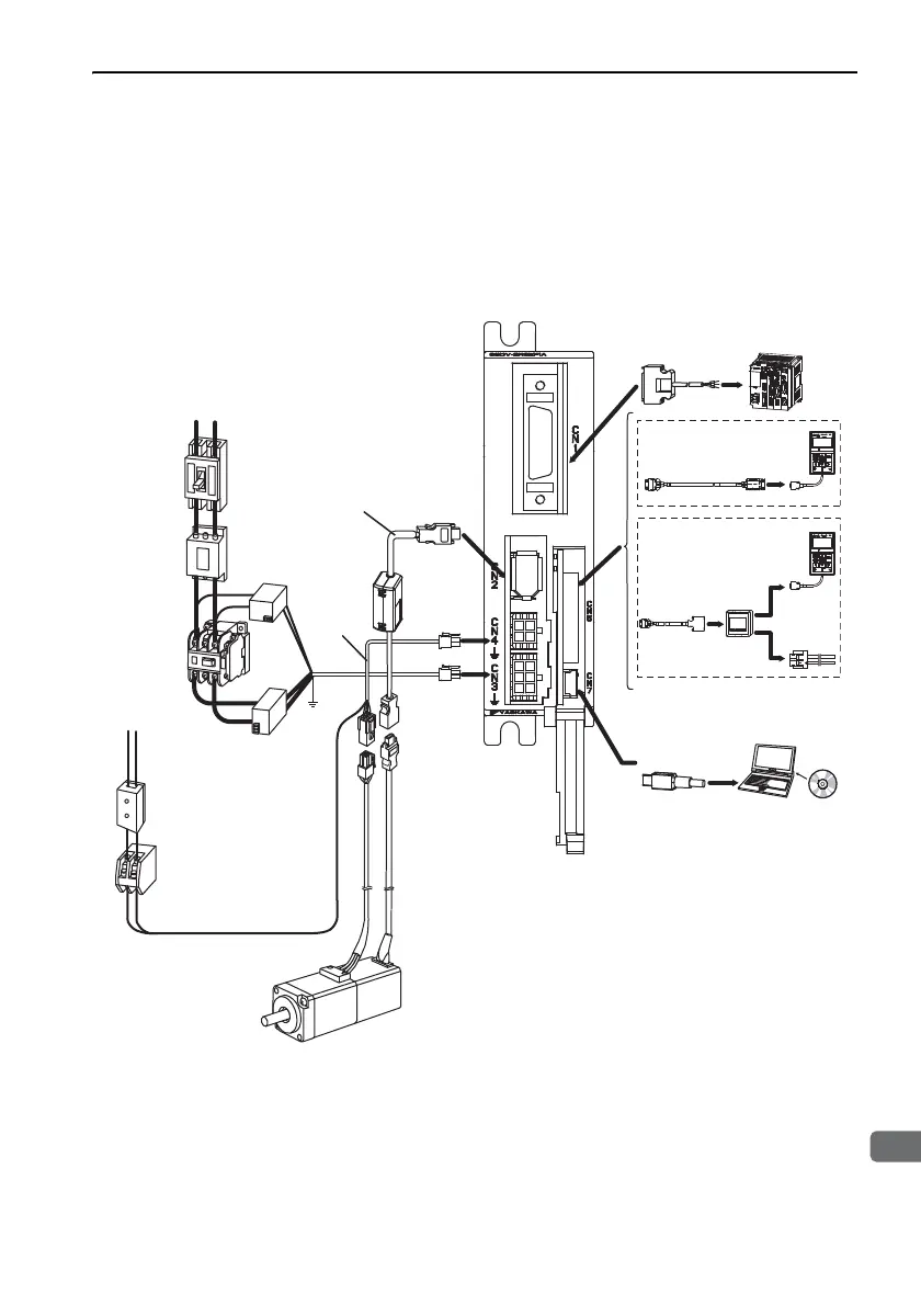
3.2.1 Connecting to SGDV-E1A SERVOPACK (Analog
Voltage/Pulse Train Model)
∗ Use a 24-VDC power supply. (Not included.)
R T
Relay cable for
digital operator
Non-isolated
AC/DC converter
for control power supply
Non-isolated
AC/DC converter
for main circuit power
supply
Power supply
cable
Grounding
wire for
power
supply
SGM7M, SGMMV Servomotor
SGDV-ES1A
SERVOPACK
or
SGDV-EP1A
SERVOPACK
Connection
cable for
analog
monitor unit
Analog
monitor
unit
Cable for
analog
monitor
100/200 VAC
VCMP
SVON COINTGON
REF
CHARGE
ALARM
DATA
JOG
SVON
SCROLL
MODE/SET
RESET
SERVO
READ
WRITE
SERVO
YASKAWA
DIGITAL OPERATOR
JUSP−OP05A−1−E
VCMP
SVON COINTGON
REF
CHARGE
ALARM
DATA
JOG
SVON
SCROLL
MODE/SET
RESET
SERVO
READ
WRITE
SERVO
YASKAWA
DIGITAL OPERATOR
JUSP−OP05A−1−E
Power supply
Single-phase 100/200 VAC
Noise filter
Molded-case
circuit breaker
(MCCB)
Protects the power
line by shutting the
circuit OFF when
overcurrent is
detected.
Eliminates
external noise from
the power line.
Magnetic
contactor
Turns the servo
ON and OFF.
Install a surge
absorber.
Brake power supply
∗
Used for a servomotor
with a brake.
Encoder cable
Connection cable
for personal
computer
Digital
operator
Digital
operator
Personal
computer
Host controller
I/O signal cable
Battery case
(when an absolute
encoder is used.)
Servomotor
main circuit
cable
Brake relay
Turns the brake power supply
ON and OFF.
 Loading...


