3 Wiring and Connection
3.3.1 Names and Functions of Main Circuit Terminals
3-6
3.3 Main Circuit Wiring
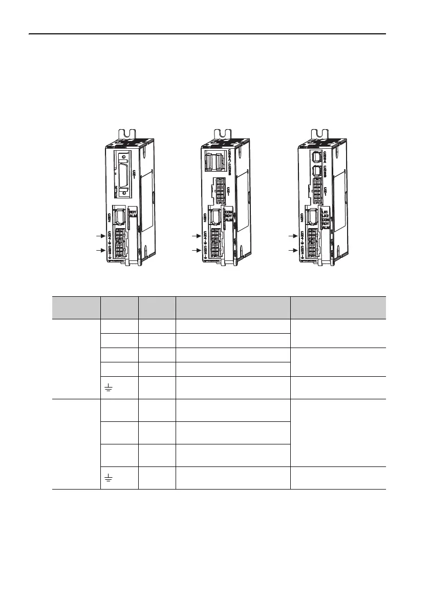
The names, specifications, and functions of the main circuit terminals required for
trial operation are given below.
3.3.1 Names and Functions of Main Circuit Terminals
Analog Voltage Models/
Pulse Train Models
M-II Models M-III Models
CN4
CN3
CN4
CN3
CN4
CN3
Connector
Terminal
Symbols
Pin No. Name Description
CN3
L1 6 Main circuit input terminal (+)
24 VDC ± 15% or
48 VDC ± 15%
L2 3 Main circuit input terminal (-)
C1 5 Control power input terminal (+)
24 VDC ± 15%
C2 4 Control power input terminal (-)
1, 2 Ground terminal
Connect to the ground ter-
minal of the power supply.
CN4
U1
Servomotor connection terminal
(phase U)
Connect to the servomotor.V2
Servomotor connection terminal
(phase V)
W3
Servomotor connection terminal
(phase W)
4 Ground terminal
Connect to the ground ter-
minal of the servomotor.
 Loading...


