FORM 100.50-NOM7 (808)
19
JOHNSON CONTROLS
3
CONSTANT VOLUME SEQUENCE OF OPERATION
Under Constant Volume (CV) operation, the unit will
be controlled from one of the following sources in order
of priority:
• 7-Wire Thermostat.
• Space Sensor.
The controller will monitor each source and self-con-
gure to the source available with the highest priority.
Thermostat Control In CV Operation
Under thermostat control, the unit will monitor the G,
Y1, Y2, W1, and W2 thermostat inputs and control the
unit accordingly. Cooling Operation with Y1 and Y2
thermostat inputs are as follows:
Compressor Staging - ON:
• Y1 Only – Cooling Stage 1 – All compressors on
System 1.
• Y1 and Y2 – Cooling Stage 2 – All of the installed
compressors on System 1 and System 2.
• If Y2 is present without Y1, rst start Cooling Stage
1, then start Cooling Stage 2.
Compressor Staging – OFF:
• Y2 O – Shut Cooling Stage 2 o - System 2 com-
pressors shut down.
• Y1 O – Shut Cooling Stage 1 o - All compressors
on System 1 shut down.
Heating Operation with W1 and W2 Inputs
The controller can be congured for two types of heat;
stepped heat (Gas or Electric) and hydronic heat (Hot
Water or Steam). Both stepped heat and hydronic heat
will be controlled to a low and high setpoint as indicated
by Heating Stage 1 and Heating Stage 2, respectively.
The controller will determine Heating Stage based on
the W1 and W2 thermostat inputs as follows:
• W1 Active Only – Heating Stage 1.
• W1 and W2 Active – Heating Stage 2.
• W2 Active Only – Heating Stage 2.
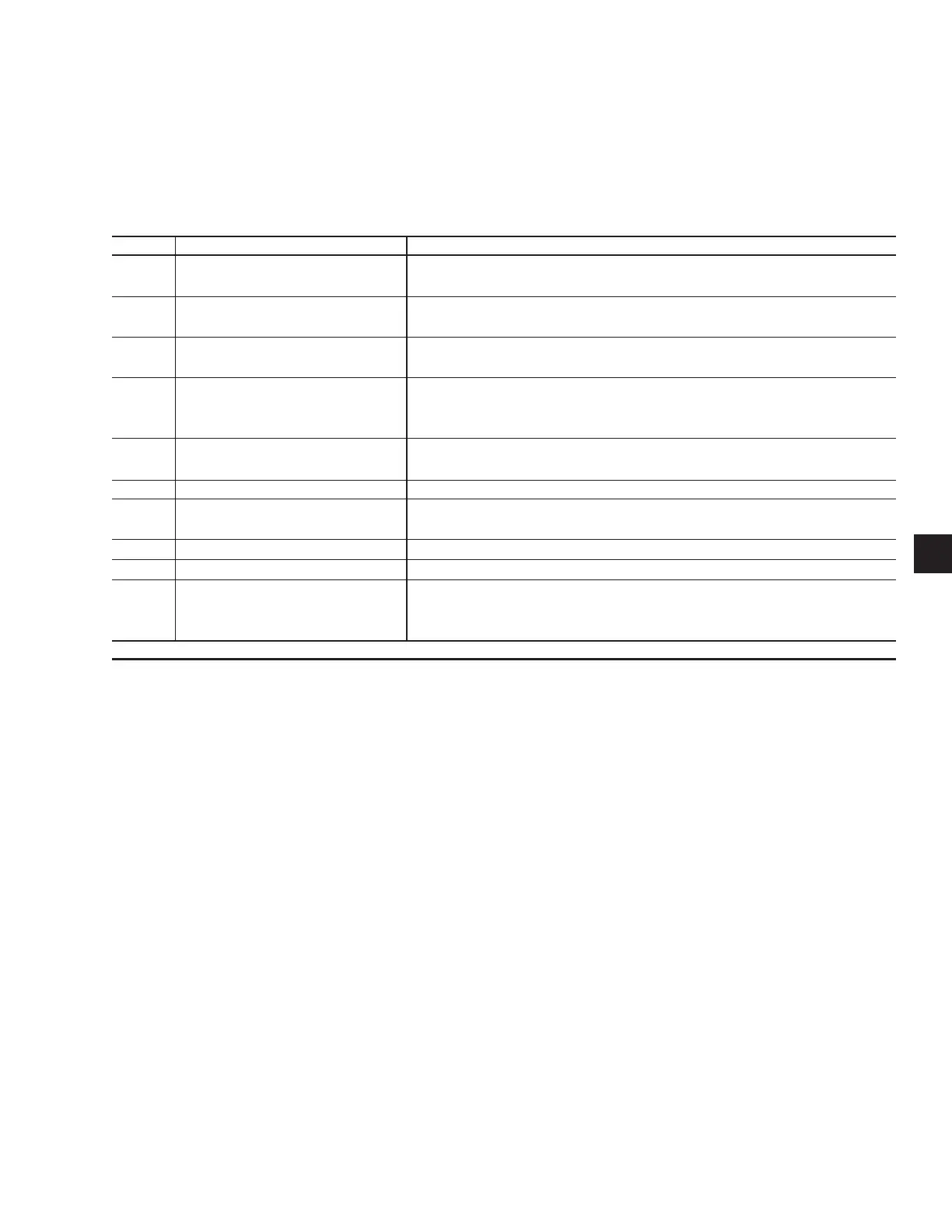
TIMEOUTS AND DELAYS
Table 2 lists the timeouts and delays that are to apply in
all functions unless an exception for a specic function
is specied.
TABLE 2 – TIMEOUTS AND DELAYS
Number Timeout or Delay Description
1 ASCD for cooling This “minimum OFF time” delay will not allow any compressor to turn on, un-
less it has been o for 5 minutes, except when ASCD override is ON.
2 ASCD for SAT trip (cooling) This will not allow any compressor to turn ON after an excessive SAT trip
has occurred, until it has been o for 5 minutes.
3 ASCD for SAT trip (heating) This will not allow any heat stage to turn ON after an excessive SAT trip has
occurred, until it has been o for 5 minutes.
4 ASCD for heating This “minimum OFF time” delay will not allow any heating stage to turn on,
unless it has been o for 2 minutes. Exception: Supply Air Tempering = 1
min.
5 Energy Saver Delay This is a 1 minute minimum time between turning on
compressor stages or heating steps.
6 Minimum Run Time for Cooling A minimum run time of 3 minutes will apply to all compressors.
7 Supply Fan ASCD This will not allow the Supply Fan to turn ON unless it has been OFF for 30
seconds.
8 Exhaust Fan Minimum Run Time The exhaust fan will have a minimum ON time of 10 seconds.
9 Exhaust Fan Minimum O Time The exhaust fan will have a minimum OFF time of 1 minute.
10 Delay to allow SAT to stabilize A 5 minute delay will be used any time a compressor, or a heating stage is
turned ON, or OFF, before using the SAT reading for any control decisions.
 Loading...