FORM 100.50-NOM7 (808)
53
JOHNSON CONTROLS
55
Cmfrt Vent High SAT
This is the SAT High Limit Setpoint for the Comfort
Ventilation mode.
Cmfrt Vent Low SAT
This is the SAT Low Limit Setpoint for the Comfort
Ventilation mode.
Warm-Up RAT
This is the Morning Warm Up Return Air Temperature
Setpoint.
Hydro Heat 1
st
Stage
CV Hydronic Heating:
When the Hydronic Heat option is enabled, the
control will maintain this SAT setpoint during a
call for rst stage Heating, by modulating the Hot
Water Valve.
VAV Heating:
This setpoint will also be the reset temperature when
operating a VAV unit in the Heating mode.
Hydro Heat 2
nd
Stage
When the Hydronic Heat option is enabled, the control
will maintain this SAT setpoint during a call for second
stage Heating, by modulating the Hot Water Valve.
OA Damper Min Pos #1
This tells the control what the minimum Outdoor Air
Damper (Economizer) position is during the occupied
mode and when the Supply Fan is at full ow. This value
will be used for CV units and VAV units.
On VAV units, this value will be used for the minimum
damper position when the VFD output from the control
is 100% (10VDC). Reason: full air ow with a VAV unit
will be equivalent as a CV unit which runs at it’s design
(maximum) fan speed.
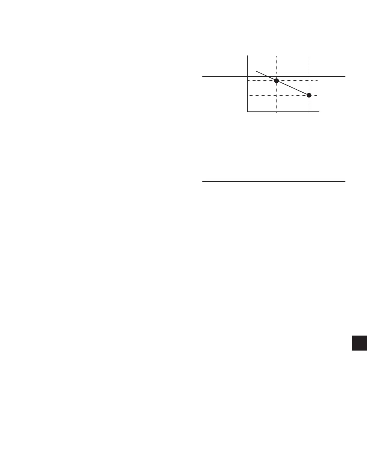
OA Damper Min Pos #2
This tells the control what the minimum Outdoor Air
Damper position is during both the occupied and un-
occupied mode and when the Supply Fan is not at full
ow. This value will be used for VAV units only and will
be ignored on CV units. Reason: when using a VAV and
operating at less then full ow, the OA dampers need to
open further to supply the required minimum air ow.
This value will indicate what the minimum position of
the OAD should be when the VFD output is at 50%. This
value will be used with the OAD Minimum Position
#1 value to linearly reset the position of the OAD with
respect to the output to the VFD. See Fig. 18.
FIG. 18 – ODA DAMPER POSITION VS. VAV
SUPPLY FAN OUTPUT
#2: 30%
#1: 15%
50%
100%
VFD OUTPUT
OD A DAMPER
PO SITION
(Default
Values)
ODA DAMPER POSITION VS.
VAV SUPPLY FAN OUTPUT
LD06585
Demand Ventilation
This setpoint is the maximum IAQ (CO2) level that the
control will allow.
FlexSys MSAT
The Mixed Supply Air Temperature Setpoint is the set-
point for the temperature of the supply air leaving the
FlexSys congured rooftop unit.
FlexSys Min Dewpt Di
The (FlexSys) Min Dewpt Di setpoint will be to de-
termine if the Evaporator Discharge Air Temperature
Setpoint should be reset between the VAV Cool High
Temp and VAV Cool Low Temp Setpoints.
UNIT SETUP KEY PARAMETERS
These setpoints are user setpoints that are intended to
be programmed in the eld.
Language
The unit will have six selectable options for the display
of parameter descriptions: English, Spanish, French,
Portuguese, German and Italian.
Measurement Units
The units and values displayed for numeric parameters
will be selectable as US Imperial units (Imperial), SI
Canada units (SI Canada) or SI units (SI). SI Canada
and SI are the same conversions except for airow.
 Loading...