JOHNSON CONTROLS
72
FORM 100.50-NOM7 (808)
Service
tion, the technician can insert a tee into the pneumatic
tubing to connect a manometer and verify the pressure
being applied to the transducer. Once this pressure is
known, a comparison can be made of the duct pressure
vs. output volts DC from the transducer. A practical and
quick check of this transducer can also be accomplished
by removing the pneumatic tubing lines from both high
and low side connections on the transducer. Since both
of the inputs will now be exposed to the same pressure,
the dierential pressure will be zero, and output 2.5
VDC according to the Table 10.
TABLE 10 – BUILDING PRESSURE TRANSDUCER
OUTPUT TABLE
BUILDING PRESSURE TRANSDUCER OUTPUT
DIFFERENTIAL INPUT OUTPUT VOLTAGE
PRESSURE - IWG - VDC
-0.50 0.00
-0.40 0.50
-0.30 1.00
-0.20 1.50
-0.10 2.00
0.00 2.50
0.10 3.00
0.20 3.50
0.30 4.00
0.40 4.50
0.50 5.00
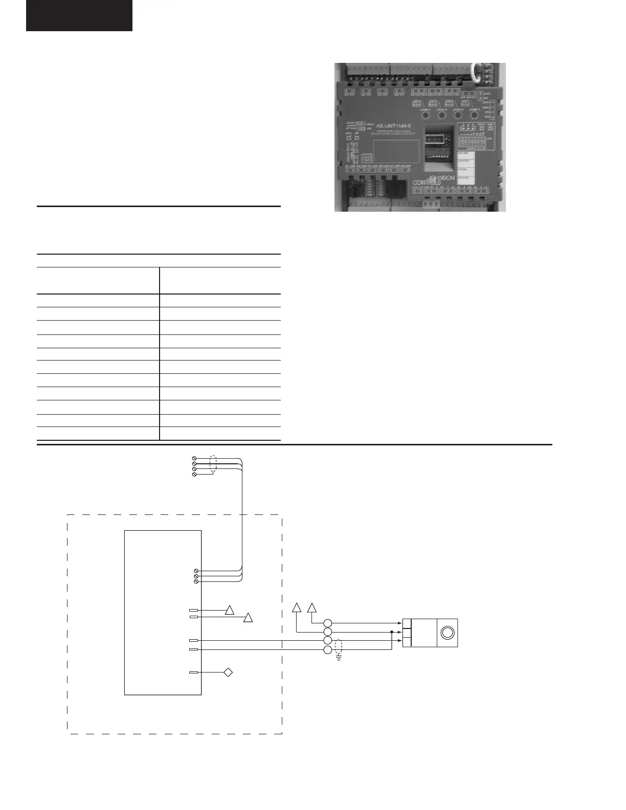
FIG. 23 – MOD-UNT
00492VIP
FIG. 24 – MOD-UNT WIRING DIAGRAM
4ACU (OPTIONAL)
FLEXSYS BYPASS
DAMPER ACTUATO
24 VAC
COM
0-10 VDC
SECONDARY CONTROLLER AND COMMUNICATIONS CABLE
REQUIRED FOR UNITS EQUIPPED FOR FLEXSYS OPERATION
SECONDARY
CONTROLLER
(MOD-UNT)
{
TB3
1
2
3
4
N2+
N2-
N2 GND
SHIELD
{
N2+
N2-
N2 GND
TB4
100
COM
W20
W23
24 VAC(W56)
RTN (W55)
W36
EVR
27
LINE # 308
LINE # 308
(TO LINE # 305)
CTB2
4
3
2
1
47
48
49
50
LD07414UU
 Loading...