74 YORK INTERNATIONAL
FORM 201.18-NM1 (102)
RE
MMENDE
P
WE
PENIN
533 HIGH
(Power Wirin
must us
this opening for any
Sin
le-Point options.
1
1
7
1
18
NTR
241 HIGH
PENIN
MI
R
MP
TE
NTR
L
ENTE
PTI
N
PANE
NTR
TRAN
F
RME
ERVI
E
WIT
2
2
48
EDGE O
NIT T
LER
CONNECTION
Technical Data
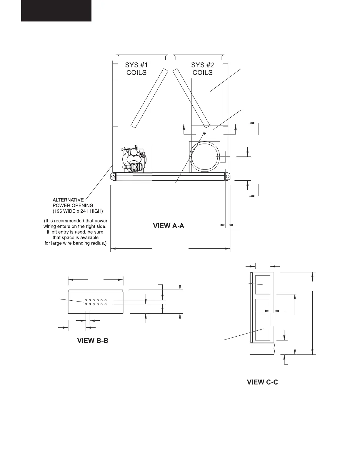
DIMENSIONS - YCAS0130 - 0180 (SI)
FIG. 33 – MODEL 0130 - 0180 DIMENSIONS (SI DIMENSIONS)
NTR
L ENTR
12
22 DIA
KN
K
T
22
1 TYP
LD02991
LD02992
LD02993
NOTES:
1. Placement on a level surface free of obstructions (including snow, for winter operation) or air
recirculation ensures rated performance, reliable operation and ease of maintenance. Site re-
strictions may compromise minimum clearances indicated below, resulting in unpredictable air
flow patterns and possible diminished performance. YORK’s unit controls will optimize operation
without nuisance high pressure safety cutout; however, the system designer must consider po-
tential performance degradation. Access to the unit Micro Panel assumes the unit is no higher
than on spring isolators. Recommended minimum clearances: Side to wall - 2m; rear to wall - 2m;
control panel end to wall - 1.2m; top - no obstructions allowed; distance between adjacent units -
3m. No more than one adjacent wall may be higher than the unit.
All dimensions
are in mm unless
otherwise noted.
 Loading...