JOHNSON CONTROLS
203
SECTION 7 - OPERATION
FORM 201.23-NM2
ISSUE DATE: 09/25/2020
7
elect to increase the speed of the compressor(s) if the
error is “0” (temperature is at Setpoint), while the rate
of change of chilled liquid temperature is “positive”
(rising). The Chiller Control Board microprocessor
may also elect to hold capacity when error is “nega-
tive” (temperature is below Setpoint) because the rate
of change of chilled liquid is “positive” (rising). Table
6 on page 203 illustrates these conditions and the
loading response from the Chiller Control Board mi-
croprocessor.
Hot Water Starts
On a hot water start under "best" case conditions, as-
suming power has not been removed and the 120 sec-
ond timer does not inhibit starting, the design of the
control algorithm for a 2compressor Standard IPLV
leaving chilled liquid capacity control allows full load-
ing of a chiller in slightly more than 14 1/2 minutes,
regardless of the number of compressors. This time pe-
riod assumes load limiting does not affect the loading
sequence and the ambient is above 40°F.
Lag Compressor Operation in Load Limiting
When a single compressor is operating in current, dis-
charge pressure, suction pressure, VSD internal ambient,
or VSD baseplate temperature limiting for more than
5 minutes and chilled liquid temperature is more than
Setpoint plus CR, the Chiller Control Board micropro-
cessor will turn on the lag compressor to bring the chilled
liquid temperature within the Control Range. After 1
hour the Chiller Control Board microprocessor will shut
down the lag compressor and attempt to control tempera-
ture with only the lead compressor to satisfy the load.
OPTIONAL HIGH IPLV CAPACITY CONTROL
(Loading/Unloading and starting additional compressors)
Optional High IPLV Capacity Control is installed in
the chiller at the factory using a dedicated EPROM
(software), part # 031-02476-002, for High IPLV con-
trol. Its purpose is to control compressors as effectively
as possible, optimizing control of both the compressors
and condenser fans. If the LWT is more than the pro-
grammed Setpoint plus CR, the Chiller Control Board
microprocessor will follow the flow chart (Page 214)
to determine the number of compressors to start based
on the last run time, time off, and the rate of change
of chilled liquid temperature. The compressor(s) will
start at the minimum start frequency based on ambient
temperature (Page 214). The respective system Feed
and Drain Valves will immediately begin to control su-
perheat and liquid level in the flash tank.
High Limit (Setpoint plus CR). If the rate of change is
dropping too fast and there is potential for overshoot,
the Chiller Control Board microprocessor may elect
not to continue to increase speed.
In cases where temperature is dropping too fast when
temperature is within the desired Control Range, the
microprocessor will be required to make decisions re-
garding speed changes under conditions where the “er-
ror” and “rate” conflict. For example, the microproces-
sor may elect to decrease the speed of the compressor(s)
if the error is “0” (temperature is at Setpoint), while the
rate of change of chilled liquid temperature is falling
(negative). The Chiller Control Board microprocessor
may also elect to hold the speed when error is “posi-
tive” (temperature is above Setpoint, but not above
Setpoint plus CR) because the rate of change of chilled
liquid is “negative” (falling). Table 6 on page 203 il-
lustrates these conditions.
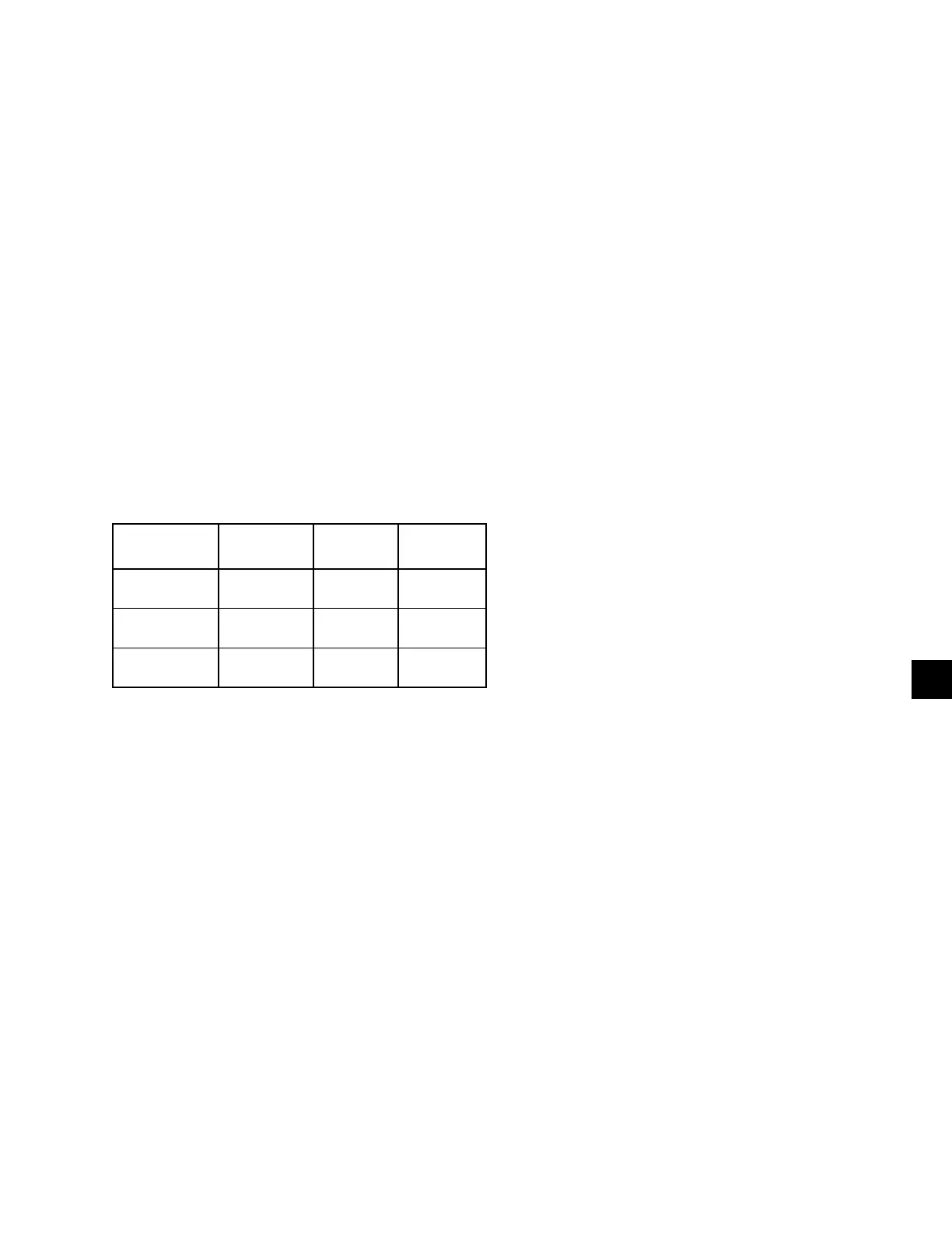
TABLE 6 - FUZZY LOGIC LOADING/UNLOADING
VS. ERROR
NEGATIVE
ERROR
ZERO ER-
ROR
POSITIVE
ERROR
NEGATIVE
RATE
UNLOAD UNLOAD HOLD
ZERO
RATE
UNLOAD HOLD HOLD
POSITIVE
RATE
HOLD LOAD LOAD
To avoid overshoot or nuisance trips on the low chilled
liquid cutout, when the temperature is below the
Setpoint – CR/2, the Chiller Control Board micropro-
cessor will reduce the speed of the compressor(s) to
unload the chiller by 2.0 Hz every 2 seconds. If tem-
perature drops to within 1.0°F above the Low Chilled
Liquid temp Cutout, the Chiller Control Board micro-
processor will unload the compressors at the rate of 4.0
Hz every 2 seconds.
As the temperature rises the microprocessor’s fuzzy
logic will factor in the rate of change before continuing
to unload. If the rate of change is rising too fast and
there is potential for a positive overshoot, the Chiller
Control Board microprocessor may elect not to con-
tinue to decrease speed.
In cases where temperature is rising too fast, when
temperature is within the desired Control Range, the
Chiller Control Board microprocessor will be required
to make decisions regarding speed changes under con-
ditions where the “error” and “rate” conflict. For ex-
ample, the Chiller Control Board microprocessor may