JOHNSON CONTROLS
212
FORM 201.23-NM2
ISSUE DATE: 09/25/2020
SECTION 7 - OPERATION
CONDENSER FAN CONTROL
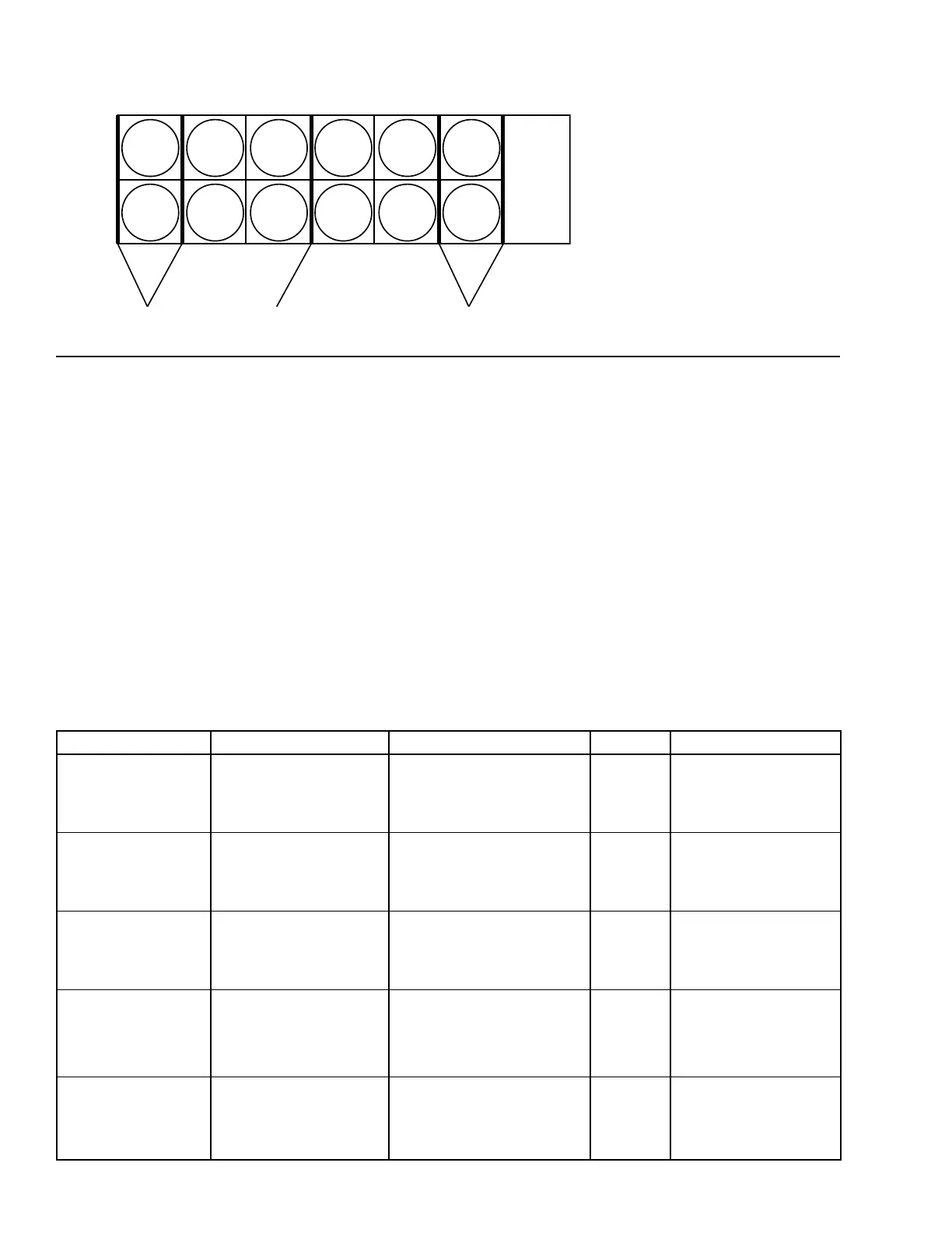
Condenser Fan control on each system is based on dis-
charge pressure. There are up to five possible stages of
fan control utilizing 3 outputs per system. Depending
upon the chiller model, there will be 4, 5, or 6 fans
per system. The fan nearest the discharge liquid head-
er will always be the first fan on a system to start. As
fan stages increment or decrement, a single fan or pair
of fans contained within a pair of fan baffles will be
turned on or off. The diagram above shows the loca-
tion of the fan baffles. These baffles will not change
location regardless of the number of fans on a chiller.
TABLE 13 - FAN STAGES AND CORRESPONDING OUTPUTS
4 FANS 5 FANS 6 FANS OUTPUT CONTACTORS
Stage 1
(1 Fan ON)
Sys 1 Fan 1
Sys 2 Fan 2
Stage 1
(1 Fan ON)
Sys 1 Fan 1
Sys 2 Fan 2
Stage 2
(2 Fans ON)
Sys 1 Fans 1 & 11
Sys 2 Fans 2 & 12)
1
Sys 1: 4CR
Sys 2: 7CR
Stage 2
(2 Fans ON)
Sys 1 Fans 3 & 5
Sys 2 Fans 4 & 6
Stage 2
(2 Fans ON)
Sys 1 Fans 3 & 5
Sys 2 Fans 4 & 6
- 2
Sys 1: 5CR
Sys 2: 8CR
Stage 3
(3 Fans ON)
Sys 1 Fans 1, 3, & 5
Sys 2 Fans 2, 4 & 6
Stage 3
(3 Fans ON)
Sys 1 Fans 1, 3, & 5
Sys 2 Fans 2, 4, & 6
Stage 4
(4 Fans ON)
Sys 1 Fans 1, 3, 5, & 11
Sys 2 Fans 2, 4, 6, & 12
1 and 2
Sys 1: 4CR & 5CR
Sys 2: 7CR & 8CR
-
Stage 4
(4 Fans ON)
Sys 1 Fans 3, 5, 7, & 9
Sys 2 Fans 4, 6, 8, & 10
- 2 and 3
Sys 1: 5CR & 6CR
Sys 2: 8CR & 9CR
Stage 4
(4 Fans ON)
Sys 1 Fans 1, 3, 5, & 7
Sys 2 Fans 2, 4, 6, & 8
Stage 5
(5 Fans ON)
Sys 1 Fans 1, 3, 5, 7, & 9
Sys 2 Fans 2, 4, 6, 8, & 10
Stage 6
(6 Fans ON)
Sys 1 Fans 1, 3, 5, 7, 9, & 11
Sys 2 Fans 2, 4, 6, 8, 10, & 12
1, 2, and 3
Sys 1: 4CR, 5CR, & 6CR
Sys 2: 7CR, 8CR, & 9CR
The fan control algorithm in the Chiller Control Board
software will not skip steps as fan stages are staged
up and down. The delay between turning on or off fan
stages as discharge pressure rises and falls is 5 seconds.
The controller increments or decrements the fan stage
by one stage based on discharge pressure and fan delay
time.
Table 13 on page 212 shows the fan staging and the
outputs for each fan stage on 4, 5, and 6 fan systems.
The microprocessor fan outputs and the fan contactors
will be the same regardless of the number of fans. The
fan wiring will change to permit operation of 4, 5, or
6 fans.
12
SYS
#2
SYS
#1
10
8
6
4
2
FAN
11
FAN
9
FAN
7
FAN
5
FAN
3
FAN
1
VSD/
CONTROL
PANEL
11 FAN UNITS - OMIT FAN 12
10 FAN UNITS - OMIT FANS 11 & 12
9 FAN UNITS - OMIT FANS 10,11 & 12
8 FAN UNITS - OMIT FANS 9,10,11 & 12
FAN LOCATIONS
FAN BAFFLES FAN BAFFLESFAN BAFFLES
LD10632
FIGURE 57 - CONDENSER FAN LOCATIONS
 Loading...


