JOHNSON CONTROLS
36
FORM 201.23-NM2
ISSUE DATE: 09/25/2020
SECTION 4 - INSTALLATION
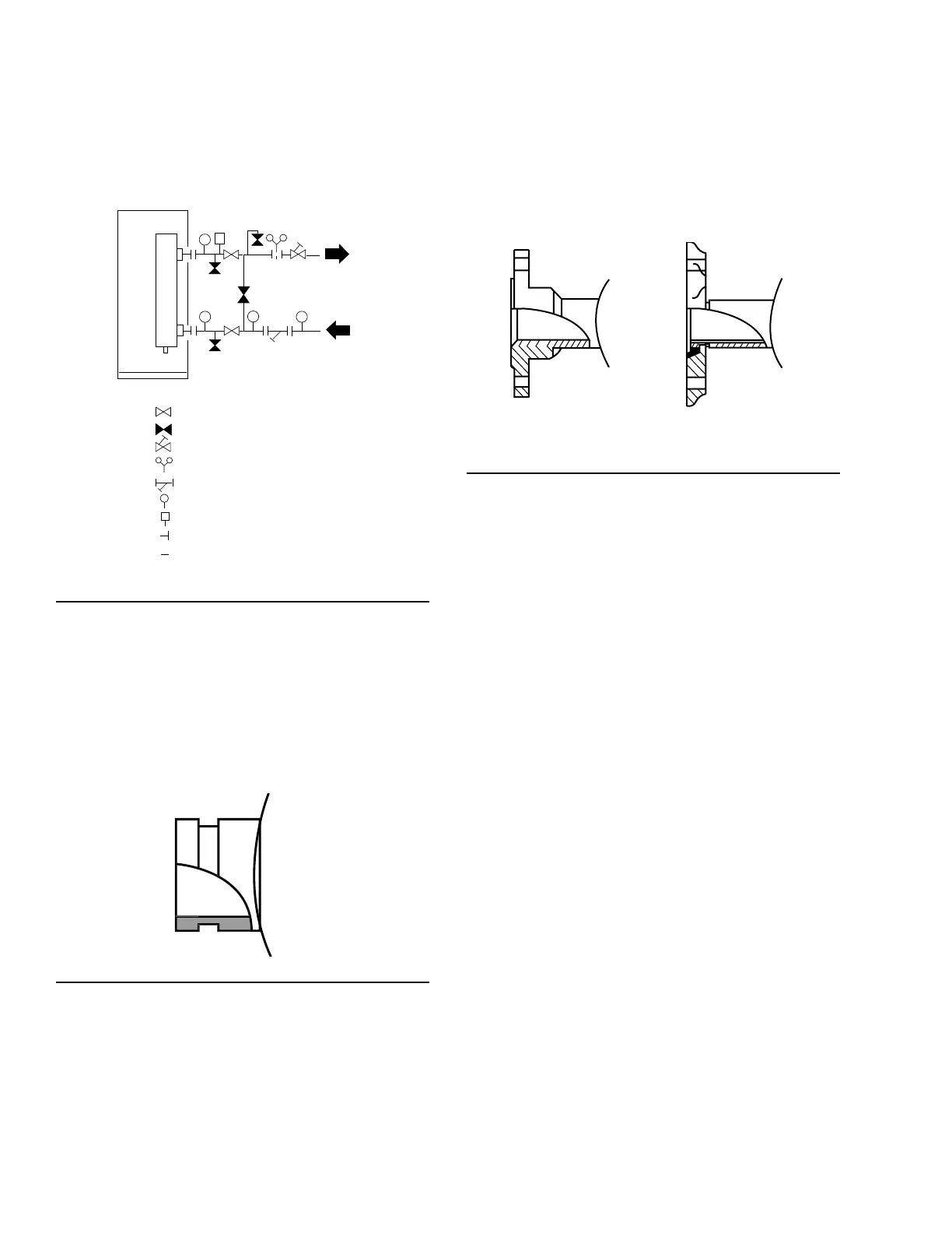
PIPEWORK ARRANGEMENT
The following is a suggested piping arrangement for
single unit installations. For multiple unit installations,
each unit should be piped as shown in Figure 5 on page
36.
-Isolating Valve - Normally Open
-Isolating Valve - Normally Closed
-Flow Regulating Valve
-Flow Measurement Device
-Strainer
-Pressure Tapping
-Flow Switch
-Flanged Connection
-Pipework
FIGURE 5 - PIPEWORK ARRANGEMENT
LD10507
CONNECTION TYPES AND SIZES
For connection sizes relevant to individual models see
SECTION 6 - TECHNICAL DATA.
COOLER CONNECTIONS
Standard chilled liquid connections on all coolers are
of the grooved type (See Figure 6 on page 36).
FIGURE 6 - GROOVED NOZZLE
LD10494
Option Flanges
One of two types of flanges may be fitted depending
on the customer or local Pressure Vessel Code require-
ments. These are grooved adapter flanges, normally
supplied loose, or weld flanges, which may be supplied
loose or ready-fitted. Grooved adapter and weld flange
dimensions are to ISO 7005 - NP10.
FIGURE 7 - FLANGE ATTACHMENT
WELD FLANGE
GROOVED ADAPTER
LD29341
REFRIGERANT RELIEF VALVE PIPING
The evaporator is protected against internal refrigerant
overpressure by refrigerant relief valves. A pressure re-
lief valve is mounted on each of the main refrigerant
lines connecting the cooler to the compressors.
A piece of pipe is fitted to each valve and directed so
that when the valve is activated the release of high
pressure gas and liquid cannot be a danger or cause
injury. For indoor installations, pressure relief valves
should be piped to the exterior of the building.
The size of any piping attached to a relief valve must
be of sufficient diameter so as not to cause resistance to
the operation of the valve. Unless otherwise specified
by local regulations. Internal diameter depends on the
length of pipe required and is given by the following
formula:
D5 = 1.447 x L
Where:
D = minimum pipe internal diameter in cm
L = length of pipe in meters
If relief piping is common to more than one valve, its
cross-sectional area must be at least the total required
by each valve. Valve types should not be mixed on a
common pipe. Precautions should be taken to ensure
the outlets of relief valves or relief valve vent pipes
remain clear of obstructions at all times.
 Loading...


