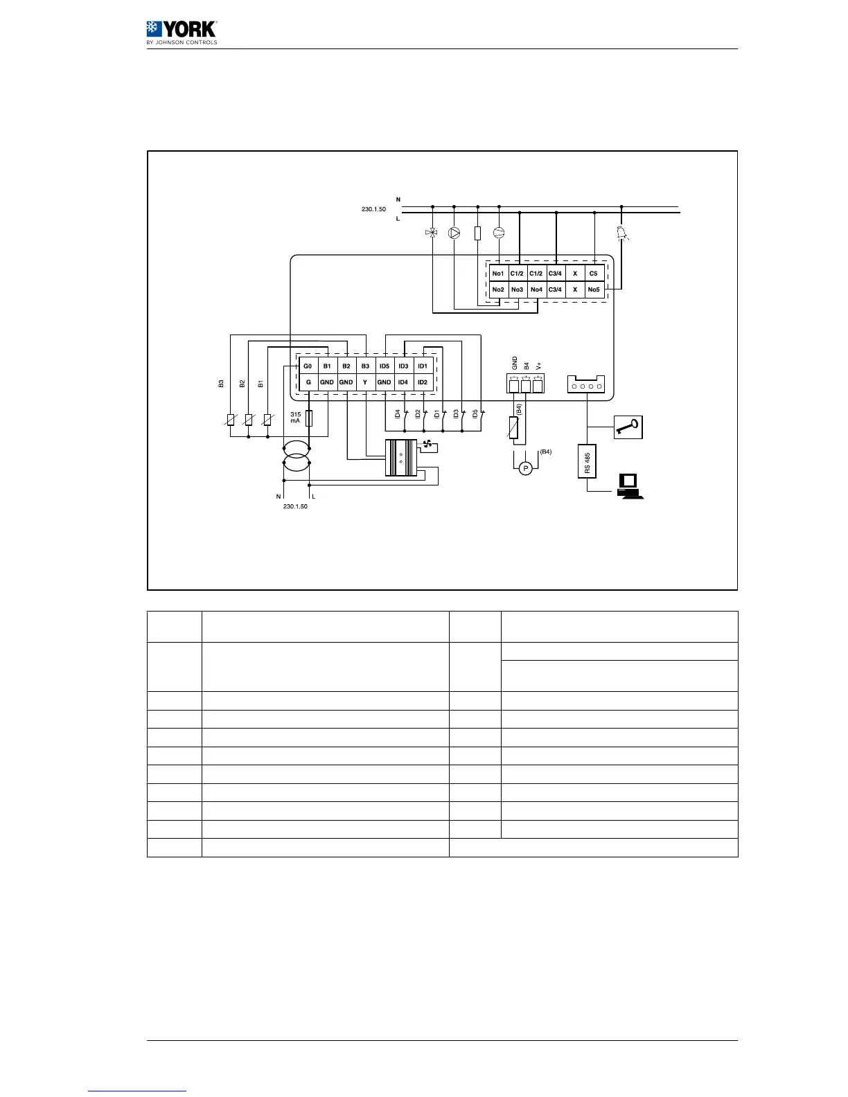
A Four-way valve B2
Water outlet temperature probe (Antifreeze pro‐
tection)
B Pump B3
Outdoor temperature probe in units with LAK
Battery probe in standard units (fan and defrost
control)
C Heater B4 Outdoor probe standard units (Dynamic Set point)
D Compressor 1 ID1 Water flow switch
E Alarm ID2 Remote COOL / HEAT
F 230 / 24 transformer ID3 High pressure switch
G Fan speed control ID4 Low pressure switch
H Communication ID5 Remote ON / OFF
I Programmable key N Neutral
J Outdoor probe standard units L Phase
B1 Water inlet temperature probe (Control set point)
(*1): When the low ambient kit (LAK) is fitted, set the B4 probe as a pressure transducer and the B3
probe as an outdoor temperature NTC probe.
User manual
1
Operating instructions µC2 1.2
9
 Loading...