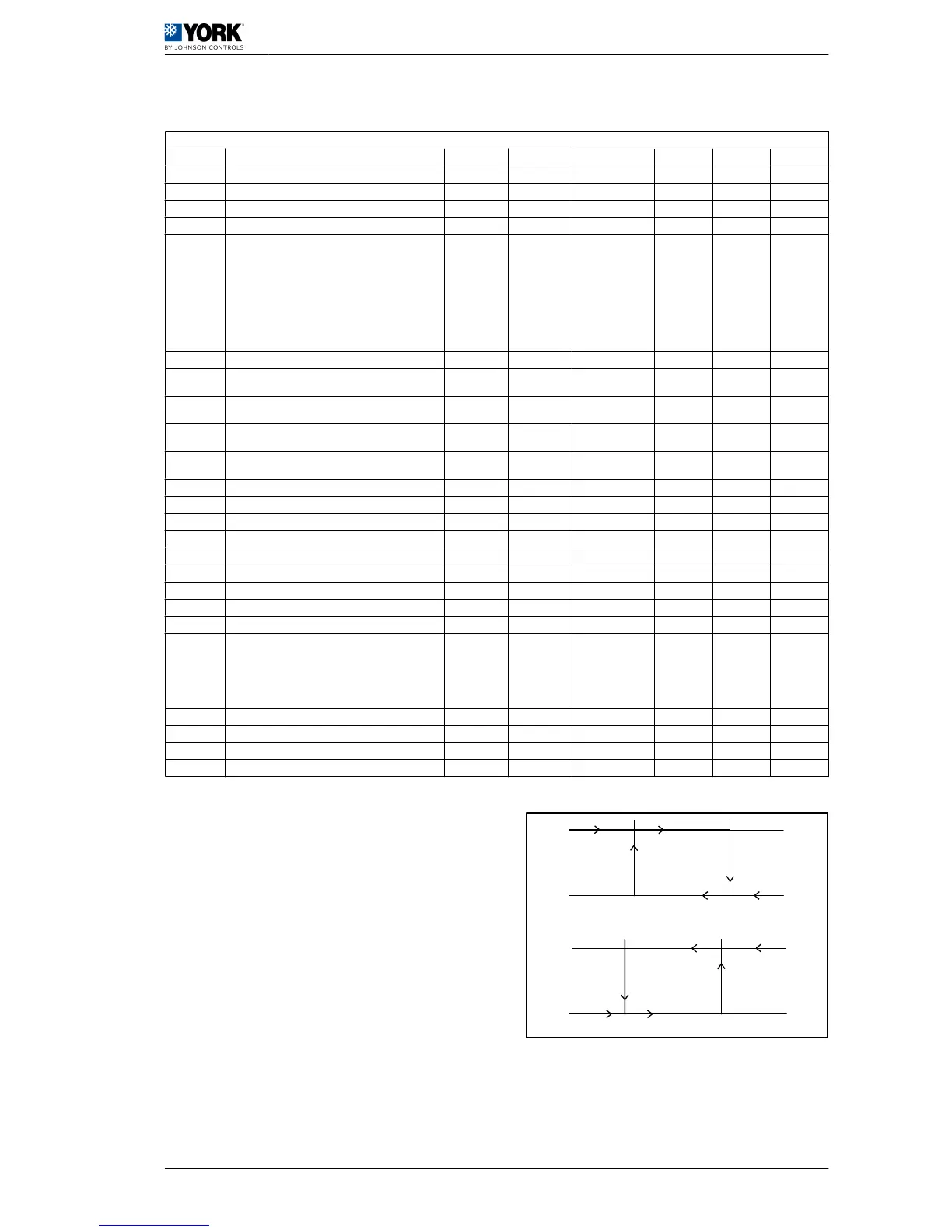
1.2.12 Controller configuration parameters
Controller configuration parameters
Display Description Level VS Unit Max. Min. Value
r01 Cool cycle set point temperature U 41 (R/W) °C r14 r13 12
r02 Cool set point temperature differential U 42 (R/W) °C 50 0,3 1
r03 Heat cycle set point temperature U 43 (R/W) °C r16 r15 40
r04 Heat cycle set point temperature differential U 44 (R/W) °C 50 0,3 2
r06
Type of regulation:
0= Proportional.Temperature
inlet.
1= Proportional + neutral zone. Inlet temp.
2= Proportional. Outlet temperature
3= Proportional + neutral zone. Outlet temp.
4= By time + dead zone. Outlet temperature (cooling
units only)
F 79 (R/W) 4 0 0
r07
Neutral zone differential F 45 (R/W) °C 50 0 1
r08
(Only if r06=4) Maximum activation time. Outlet tem‐
perature.
F 80 (R/W) Seconds 999 r09 120
r09
(Only if r06=4) Minimum activation time. Outlet temper‐
ature.
F 81 (R/W) Seconds 999 c04 100
r10
(Only if r06=4) Maximum deactivation time. Outlet tem‐
perature.
F 82 (R/W) Seconds 999 r11 120
r11
(Only if r06=4) Minimum deactivation time. Outlet tem‐
perature.
F 83 (R/W) Seconds 999 c05 100
r12 (Only if r06=4) Compressor deactivation differential. F 46 (R/W) °C 50 0 1
r13 Cool cycle minimum set point temperature U 47 (R/W) °C r14 -40 6
r14 Cool cycle maximum set point temperature U 48 (R/W) °C 80 r13 20
r15 Heat cycle minimum set point temperature U 49 (R/W) °C r16 -40 25
r16 Heat cycle maximum set point temperature U 50 (R/W) °C 80 r15 45
r17 Summer offset constant U 51 (R/W) - 5 -5 -0,4
r18 Maximum set point distance U 52 (R/W) °K 20 0,3 3,2
r19 Summer offset start temperature U 53 (R/W) °C 176 -40 32
r20 Winter offset start temperature U 54 (R/W) °C 176 -40 5
r27
Inertia tank suppression.
0= No suppression.
1=Suppression in cold cycle
2=Suppression in heat cycle.
3= Always suppressed.
F 88 (R/W) 3 0 3
r28 Minimum low pressure determining time F 89 (R/W) Seconds 999 0 210
r29 Cool cycle low pressure differential F 58 (R/W) °C 50 0,3 3
r30 Heat cycle low pressure differential F 58 (R/W) °C 50 0,3 4
r31 Winter offset constant U 60 (R/W) - 5 -5 -0,4
A Temperature D
HEAT set point (r03) + Dif‐
ferential (r04)
B Compressor E COOL set point (r01)
C HEAT set point (r03) F
COOL set point (r01) + Dif‐
ferential (r02)
 Loading...