1.2.7 Parameters relating to fans
Parameters relating to fans
Display Description Level VS Unit Max. Min. Value
F01
Fan outlet:
0= Absent (function not available
1= Present
F 10 (R/W) 1 0 1
F02
Operating mode:
0=Always ON (function not available)
1= parallel to the compressor (function not
available)
2=ON/OFF operation (function not availa‐
ble)
3= parallel to the compressor and speed
adjustment
U 48 (R/W) 3 0 3
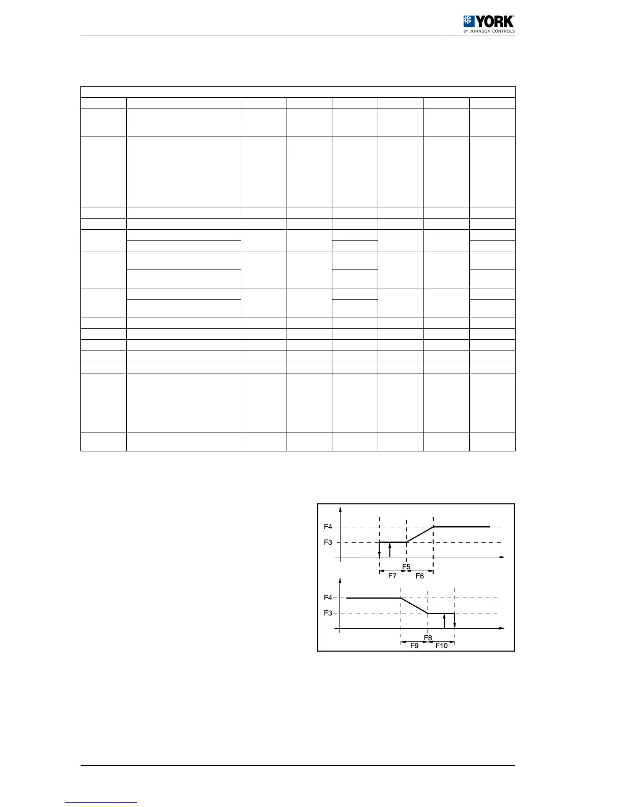
F03 Minimum Triac voltage F 49 (R/W) step F04 0 35
F04 Maximum Triac voltage F 50 (R/W) step 100 F03 85
F05
Minimum speed temp, cool cycle
F 24 (R/W)
°C
80 -40
30
Minimum speed pressure, cool cycle (1) bar 22,2
F06
Maximum speed temp differential, cool cy‐
cle
F 26 (R/W)
°C
50 0
15
Maximum speed pressure differential, cool
cycle (1)
bar 3,7
F07
Fan stoppage temp differential, cool cycle
F 28 (R/W)
°C
50 0
10
Fan stoppage pressure differential, cool cy‐
cle (1)
bar 6,5
F08 Minimum speed temp, heat cycle F 30 (R/W) °C 80 -40 6
F09 Maximum speed differential, heat cycle F 32 (R/W) °C 50 0 3
F10 Fan stoppage temp differential, heat cycle F 34 (R/W) °C F08 0 6
F11 Fan start-up time F 51 (R/W) Seconds 120 0 10
F12 Triac impulse duration F 52 (R/W) Seconds 10 0 2
F13
Fan management in defrost mode:
0= fan disabled
1= fan enabled in cool cycle mode (function
not available).
2= fan disabled until the defrost end tem‐
perature is reached and with top-speed
start-up during d16
F 53 (R/W) 2 0 2
F14
Fan operating when starting with high am‐
bient temperature
U 91 (R/W) Seconds 999 0 30
(1) Parameters to be checked when pressure probes are to be used (low ambient accessory) YLCA 5 to 15.
A Fan speed
B Condensing temperature
C Evaporation temperature
 Loading...