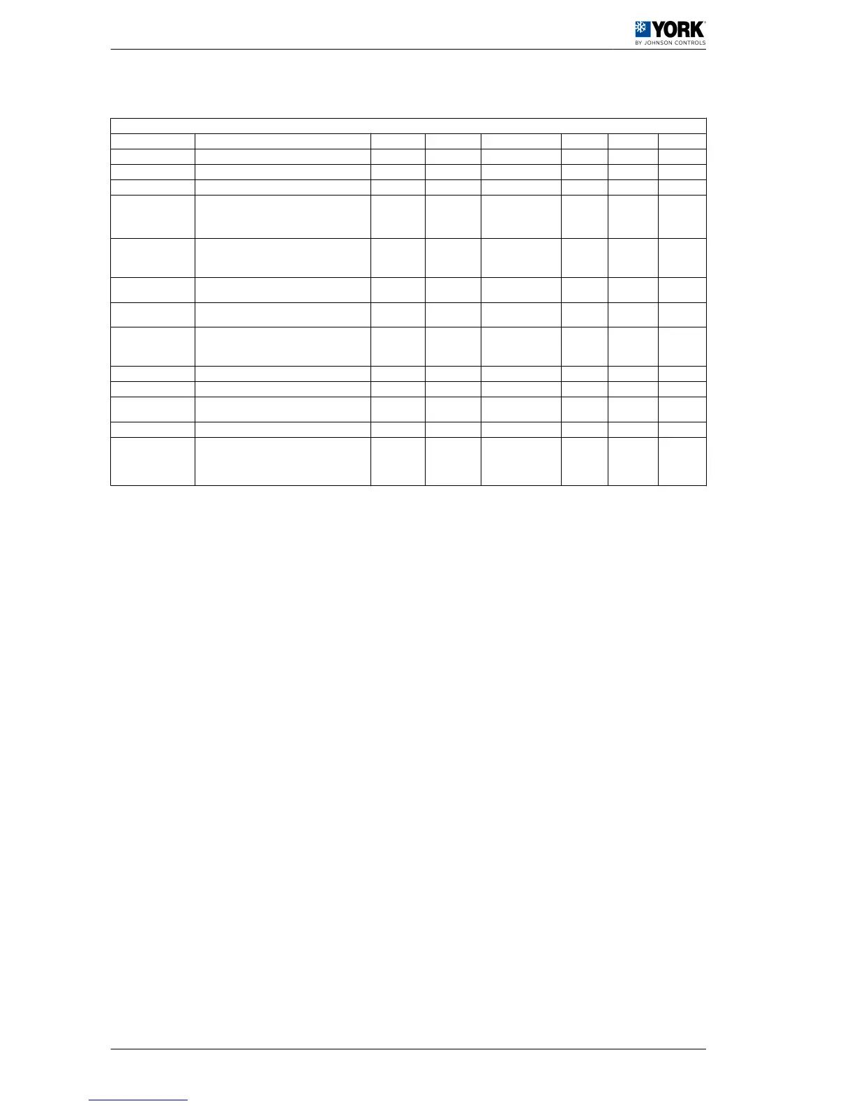
1.2.11 Alarm configuration parameters
Alarm configuration parameters
Parameters Description Level VS Unit Max. Min. Value
P01 Alarm delay by flow switch at start-up. U 63 (R/W) Seconds 150 0 20
P02 Alarm delay by flow switch with unit in operation. U 64 (R/W) Seconds 120 0 5
P03 Alarm delay by low pressure switch at start-up. U 65 (R/W) Seconds 200 0 60
P05
Alarm reset
6= High and low pressure switch manual reset at
third activation in one hour. Antifreeze control is
manually reset
F 67 (R/W) 6
P06
Cool and heat cycle symbols:
1= "Sun" heat cycle, "Snowflake" cool cycle
0= "Sun" cool cycle, "Snowflake" heat cycle
F 19 (R/W) 1 0 1
P08
Digital input 1 for flow switch. Do not modify this
parameter
F 69 (R/W) 1
P09
Digital input 2 for the remote COOL/HEAT func‐
tion. Do not modify this parameter
F 70 (R/W) 9
P15
Low pressure alarm selection:
0= Inoperative with the compressor OFF
1= Operative with the compressor OFF
F 76 (R/W) 1 0 1
P16 High-temperature alarm for return water U 38 (R/W) °C 80 -40 30
P17 High-temperature delay at start-up U 77 (R/W) Minutes 250 0 30
P18
High pressure alarm by transducer:
0= Function disabled
F 39 (R/W) bar 99,9 0,1 41
P19 Low-temperature alarm for return water U 40 (R/W) °C 80 -40 10
P20
Alarm activation for high and low water temper‐
ature at start-up:
1= function enabled
0= function not enabled
U 20 (R/W) 1 0 0
1 User manual
1.2 Operating instructions µC2
20
 Loading...