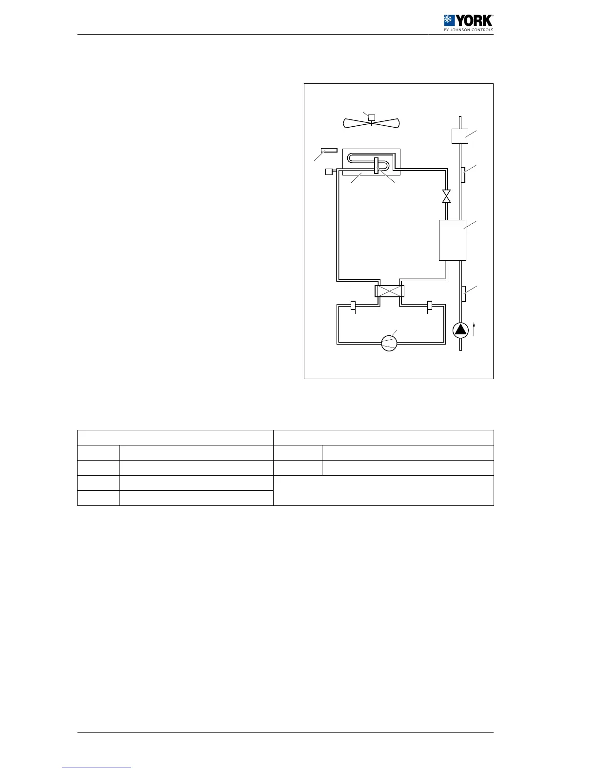
1.2.3 Control layout
A Outdoor temperature
probe:
YLCA / YLHA PLUS 5
to 15 with LAK (B3)
YLCA / YLHA PLUS 5
to 15 standard (B4)
YLCA / YLHA PLUS
20 to 27 standard
(B3)
H Low pressure switch (LP)
B Fan I Compressor
C Flow switch (FS) J High pressure switch
(HP)
D NTC water outlet
probe (B2)
K Four-way valve
E Indoor heat exchang‐
er
L Outdoor heat exchanger
F NTC water inlet probe
(B1)
M Pressure sensor (BA)
(YLCA / YLHA PLUS 5 to
20 LAK)
(YLCA / YLHA PLUS 20
to 27)
G Pump N Outdoor exchanger NTC
probe (B3)
(YLCA / YLHA PLUS 5 to
15)
Parameter tables
The following tables show the parameters and their values, divided into groups:
Parameter level codes Supervision variables
D Direct R/W Read/write parameter
U User R Read-only parameter
S Super user
F Factory
 Loading...