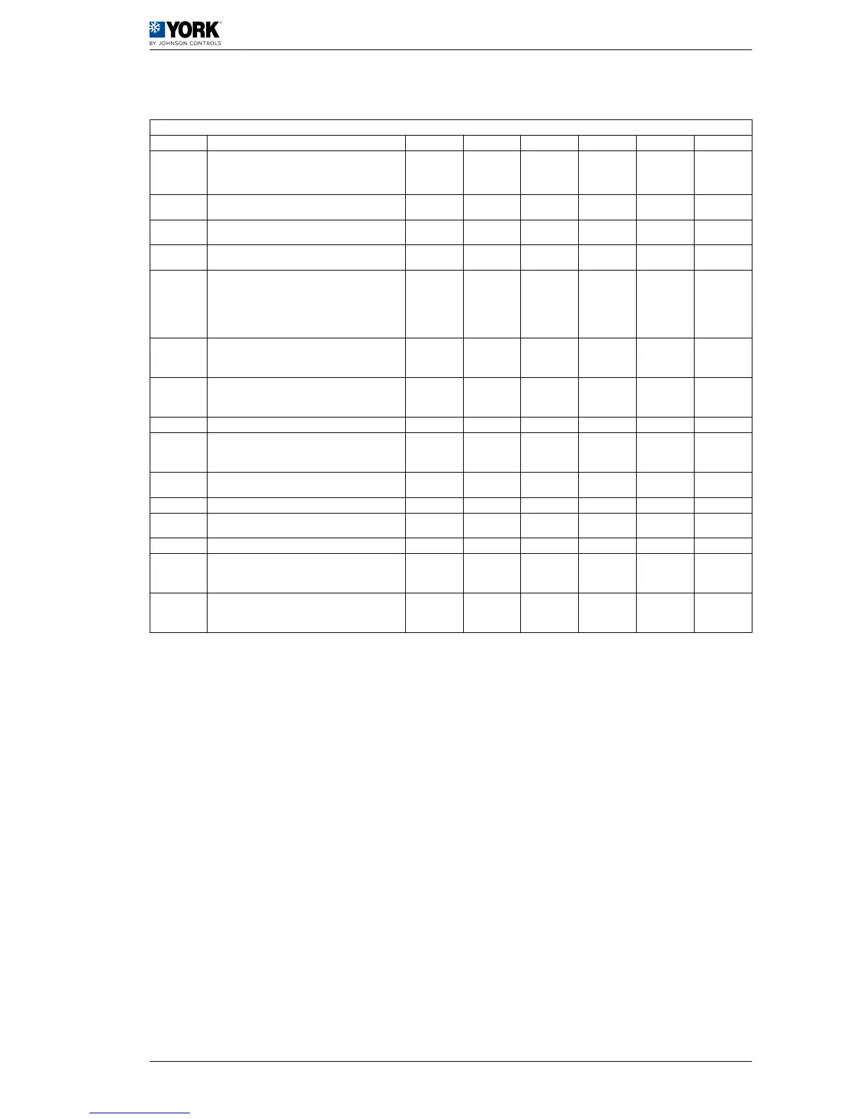
1.2.10 Unit configuration parameters
Unit configuration parameters
Display Description Level VS Unit Max. Min. Value
H01
Unit model:
2= Water cooling unit
3= Air-water heat pump
F 54 (R/W)
2
(YLCA)
3
(YLHA PLUS)
H02
Number of ventilation circuits (do not modify this pa‐
rameter)
F 12 (R/W) 0
H03
No. of evaporating units present (do not modify this
parameter)
F 13 (R/W) 0
H04
No. of compressors per circuit (do not modify this pa‐
rameter)
F 55 (R/W) 0
H05
Pump operation:
0= Absent
1= Always ON
2= ON upon controller call
3= ON upon controller and time call
F 56 (R/W) 3 0 1
H06
COOL/HEAT digital input:
0= Absent
1= Present
U 14 (R/W) 1 0 0
H07
ON/OFF digital input:
0= Absent
1= Present
U 15 (R/W) 1 0 0
H08 Network configuration (do not modify this parameter). F 57 (R/W) 3 0 0
H09
Keyboard locked:
0= Disabled
1= Enabled
U 16 (R/W) 1 0 1
H10
Serial direction for monitoring:
0= Future use as terminal
U 58 (R/W) 200 1 1
H11 Output configuration (not selectable) F 59 (R/W) 3 0 0
H12
4-way valve logic operation. Activated in cold cycle (do
not modify this parameter)
F 60 (R/W) 3 0 0
H21 Second pump function (do not modify this parameter) F 62 (R/W) 4 0 0
H22
Default parameter loading disabled:
0= Disabled
1= Enabled
F 18 (R/W) 1 0 1
H23
Modbus protocol setting:
0= Disabled
1= Enabled
F 11 1 0 0
User manual 1
Operating instructions µC2 1.2
19
 Loading...