1.2.9 Antifreeze control configuration parameters
Antifreeze control configuration parameters
Parameters Description Level VS Unit Max. Min. Value
A01 Antifreeze control set point temperature U 11 (R/W) °C - A07 3
A02 Antifreeze reset differential U 12 (R/W) °K 50 0,3 5
A03 Antifreeze alarm by-pass time U 22 (R/W) Seconds 150 0 0
A04 Antifreeze heater activation temperature U 13 (R/W) °C r16 A01 3
A05 Antifreeze heater activation differential U 14 (R/W) °K 50 0,3 2
A06
Backup heater control probe:
0= Control probe
1= Antifreeze probe
F 6 (R/W) - 1 0 0
A07
Minimum level antifreeze control set point
temperature
U 15 (R/W) °C 79 -40 3
A08
Heating heater activation set point tempera‐
ture
U 16 (R/W) °C r15 A01 3
A09
Heating heater deactivation set point temper‐
ature differential
U 17 (R/W) °C 50 0,3 3
A10
Automatic start-up by antifreeze alarm (unit in
standby):
0= Function disabled
1= Water pump + heater
2= Water pump + heater + compressor (heat
pumps only)
3= Heater
U 23 (R/W) 3 0 2
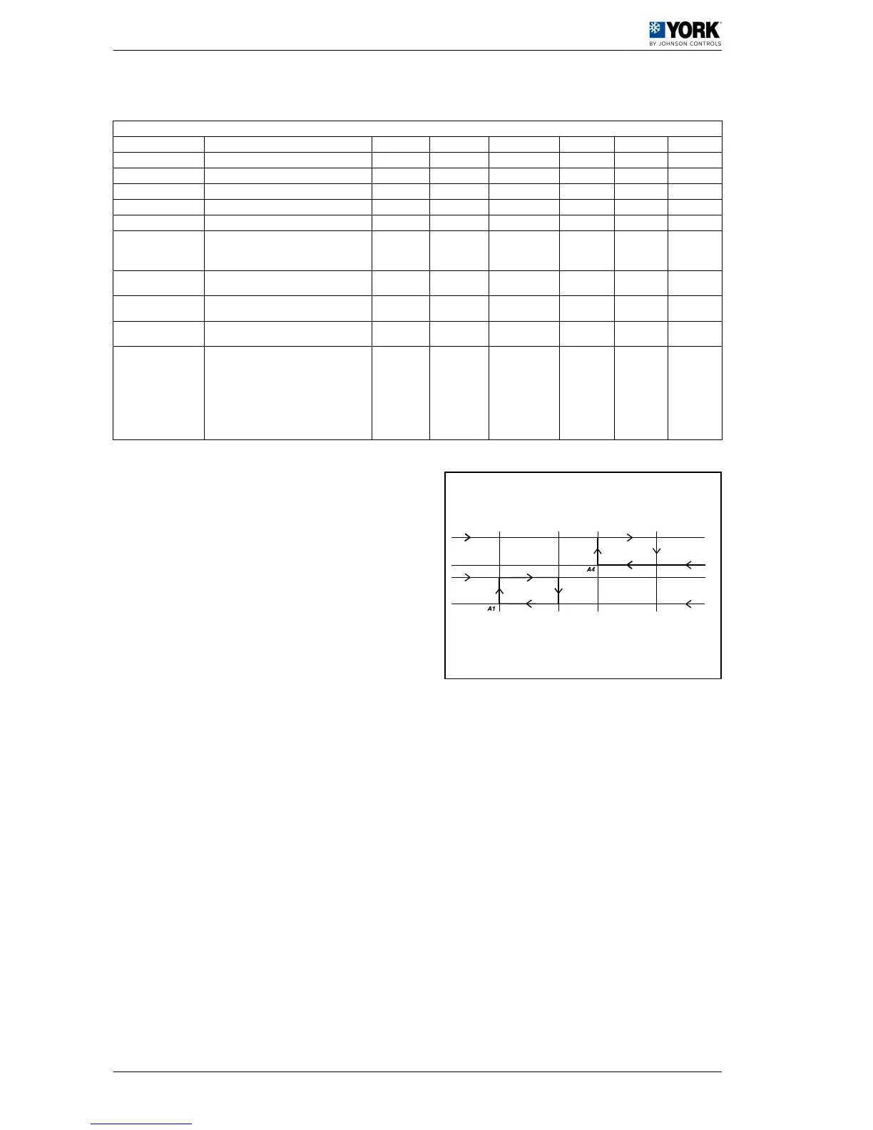
A
Antifreeze reset dif‐
ferential (A2)
D Antifreeze alarm
B
Antifreeze heater ac‐
tivation differential
(A5)
E
Antifreeze heater activa‐
tion temperature (A4)
C Heaters F
Antifreeze set point tem‐
perature (A1)
 Loading...